



























































































































































UPS selection often starts with a rough VA estimate and ends when the rack powers on. That misses the two questions Eaton emphasizes: how much load must be supported and how long it must remain supported. A unit can have adequate nameplate capacity yet provide too little runtime at the measured load, or it can be electrically incompatible with the outlet, PDU or redundant server power design.
Eaton’s sizing guidance separates real power in watts from apparent power in volt-amperes and recommends capacity above the present requirement to allow growth. Its runtime graphs show that runtime is model-, battery- and load-dependent, while its installation guidance calls out placement, ventilation, battery records and network-card monitoring. Those details belong in the design before equipment is ordered.
This deployment method produces a traceable power-protection system: an owned load inventory, selected runtime objective, documented electrical path, safe rack plan, configured load segments, monitored management path and tested shutdown sequence. ALLMSP can maintain that record as servers, switches, batteries and business continuity needs change.
For organizations in Lawrenceville, Suwanee, Gwinnett County, Metro Atlanta, and across Georgia, ALLMSP can calculate Eaton UPS load, runtime, and battery expansion before installation through one accountable in-house process for assessment, configuration, testing, and support.
Key decisions at a glance
- Measure normal, peak and startup demand in watts and VA, then map exactly which devices need battery-backed power.
- Select topology, input plug, output receptacles, capacity and runtime from the actual site rather than a model name or VA rating alone.
- Verify rack weight, airflow, electrical branch, grounding, bypass and external-battery requirements with qualified facilities personnel.
- Use load segments and redundant power paths deliberately so low-priority equipment can be shed without disabling management or recovery.
- Commission the Eaton UPS with alert, self-test, battery-transfer, graceful-shutdown and recovery evidence that another technician can repeat.
Build a Protected-Load and Runtime Worksheet

Inventory every device proposed for battery-backed outlets: servers, storage, firewalls, switches, wireless controllers, provider handoffs, management appliances and any cooling or console component required during recovery. Record normal and observed peak watts, nameplate VA or current where appropriate, power factor when known, plug type, number of power supplies, startup behavior, criticality and the shutdown dependency. Exclude laser printers, heaters and other high-inrush loads unless the exact Eaton design explicitly supports them.
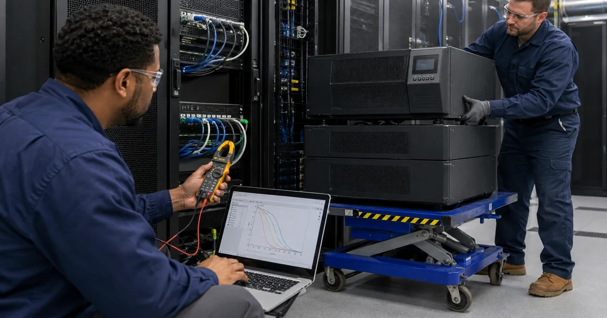
Calculate both capacity and runtime. Eaton’s sizing guide explains that watts describe real power while VA includes power factor, the UPS must satisfy both ratings. Add an explicit growth allowance rather than filling every watt on day one. Then use Eaton’s model-specific runtime curves at the projected load, with the planned number of external battery modules, instead of extrapolating from a low-load marketing figure.
Turn the business objective into minutes and actions. A closet that only needs to ride through generator transfer has a different requirement from a site that must keep connectivity alive for a carrier outage or shut down virtual hosts in sequence. Document the trigger, decision time, application shutdown duration, network dependency and battery reserve. That timeline determines whether additional runtime actually solves the problem.
- List only devices that require battery-backed operation.
- Capture observed watts, peak demand, VA and power factor where available.
- Check both the Eaton watt and VA limits.
- Use the exact model and EBM runtime curve at projected load.
- Translate runtime into a shutdown or continuity timeline.
Choose Eaton Topology, Capacity, Connections, and Battery Expansion

Choose standby, line-interactive or double-conversion topology according to equipment sensitivity, incoming power quality, transfer expectations and budget. For server and network loads, compare current Eaton families such as 5P, 5PX, 9SX and 9PX using their exact technical data. Confirm input voltage, frequency, plug and branch-circuit requirement, output voltage, receptacle types and count, watt and VA capacity, rack or tower format, load segments, external-battery support, network-card slot, and environmental limits.
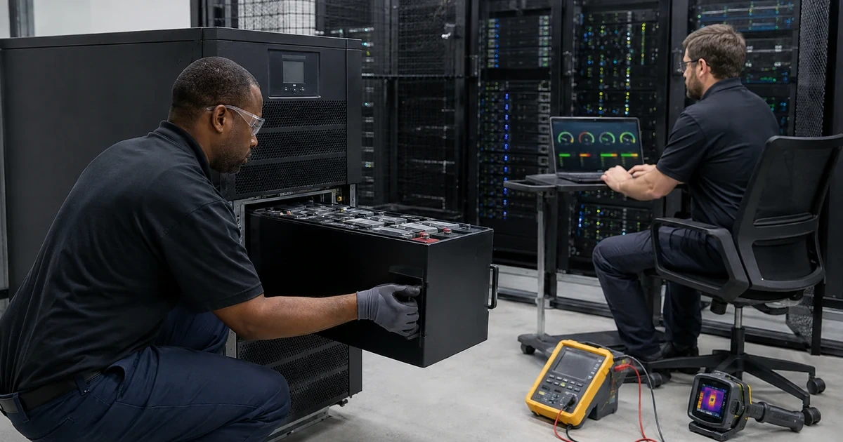
Match external battery modules to the exact UPS series and voltage. EBMs increase runtime, not output capacity, and they add rack space, weight, cabling, charging time and replacement scope. Record the supported number and arrangement, battery chemistry and model-specific installation sequence. Do not mix battery ages or references merely because connectors appear compatible.
Design redundancy as a complete power path. Dual-cord servers should not have both supplies connected to one UPS or a single downstream PDU when the objective is path resilience. Map utility source, branch circuits, UPS units, maintenance bypass where applicable, rack PDUs and device power supplies. A second UPS only adds resilience when upstream and downstream common points are understood and tested.
- Select topology from load sensitivity and power conditions.
- Verify exact input, output, watt, VA and physical specifications.
- Treat EBMs as runtime expansion, not capacity expansion.
- Match battery references and installation instructions exactly.
- Draw every shared point in redundant power paths.
Prepare the Electrical, Rack, Cooling, and Service Environment
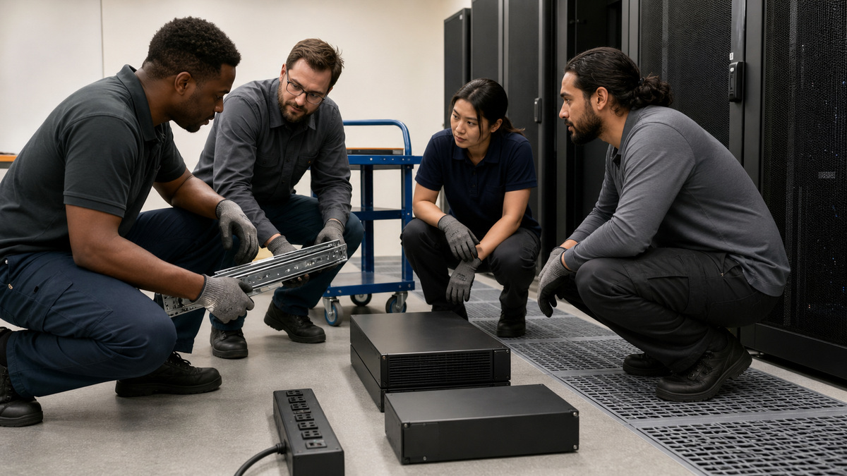
Have qualified electrical personnel verify the branch circuit, breaker, receptacle, grounding, phase, voltage and code requirements before delivery. Lock down who owns any hardwired input, bypass cabinet, emergency power-off path or generator interface. Do not solve a plug mismatch with an unapproved adapter, extension lead or daisy-chained power strip. The installed path must match the selected Eaton model and the documented design.
Plan the physical move and rack load. UPS and battery modules are dense and can exceed safe single-person handling limits. Confirm rail compatibility, rack depth, mounting hardware, floor and rack capacity, center of gravity, lifting method, front/rear service clearance and ventilation. Place heavy equipment low without blocking cool-air intake, hot-air exhaust, cable access or removal of battery modules.
Record the room temperature and airflow baseline because heat shortens battery life and reduces reliability. Keep liquids, dust and storage away from the UPS. Identify how technicians will service batteries, fans, cards and cables without disturbing live production paths. Facilities and IT should sign the final placement before the maintenance window rather than negotiate it beside an open rack.
- Validate the branch, receptacle, grounding and code with qualified staff.
- Use only approved plugs, cables, rails and bypass components.
- Calculate rack and floor loading for UPS and EBMs.
- Preserve ventilation and safe service clearance.
- Capture temperature and airflow before commissioning.
Connect Load Segments and Preserve the Management Path
Label each UPS outlet or load segment by device, power-supply side and priority. Keep the modem, firewall, core switch, management card and shutdown controller alive long enough to observe the event and complete the recovery plan. Place noncritical displays, lab equipment or secondary loads on controllable segments only when the shutdown policy explicitly sheds them before critical infrastructure.
For dual-cord devices, verify that either intended path can support the required state without overloading the surviving UPS or PDU. Check power-supply sharing behavior rather than assuming a perfect 50/50 split. Secure cables so a service action cannot unplug the wrong feed, and document which feed must remain available for remote management during a power incident.
- Label device, PSU side and priority at every outlet.
- Keep network and management dependencies powered through shutdown.
- Use load segments for deliberate load shedding.
- Test each redundant path against its surviving load.
- Photograph and document final power connections.
Commission Transfer, Runtime, Alerts, and Graceful Shutdown
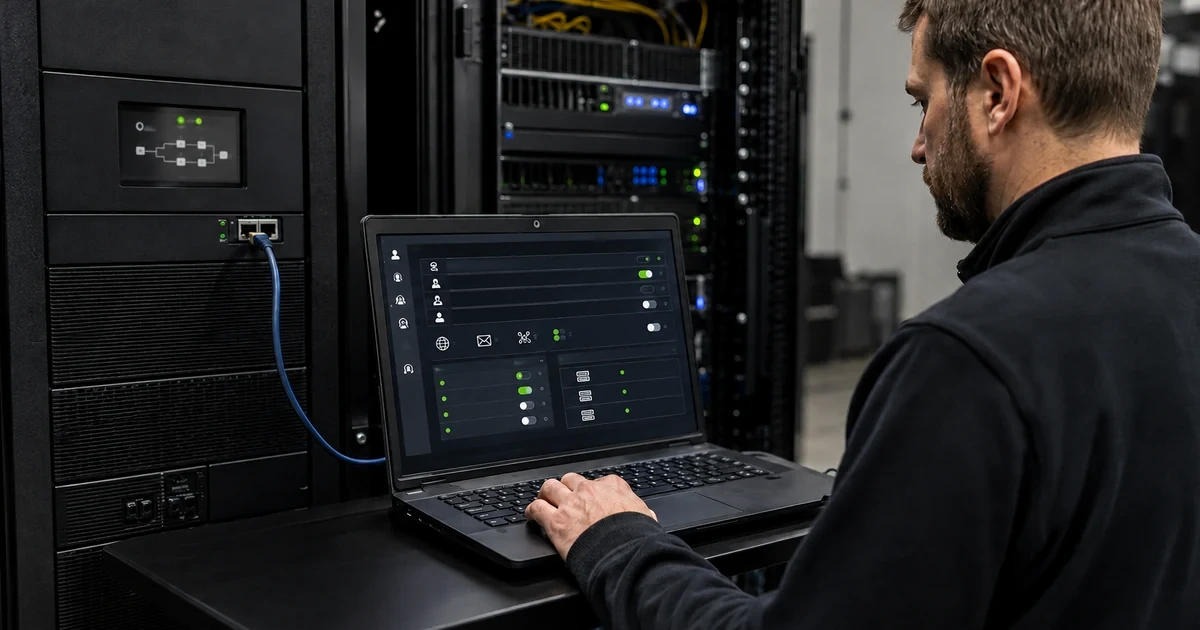
After model-specific charging and startup, confirm normal input, output, load, battery, EBM and bypass state. Configure date, time, network card, alert recipients and shutdown software before testing. Run the supported self-test in a maintenance window, then perform a controlled input-loss exercise according to Eaton guidance and site safety rules. Never disconnect conductors or defeat interlocks to simulate an outage.
Measure the event timeline: utility loss, battery transfer, alert delivery, load shedding, application and host shutdown, low-battery reserve, utility restoration and restart. Validate that recovery does not create an inrush or dependency race. Save the UPS event log, observed load and runtime, screenshots without sensitive data, and the exact test conditions so later battery degradation can be compared with a known-good baseline.
- Confirm normal state and charging before testing.
- Test only with the documented Eaton and site procedure.
- Verify alerts and shutdown actions end to end.
- Retain battery reserve for uncertainty and safe recovery.
- Save the measured commissioning baseline.
Operate the Eaton UPS as a Maintained System
Assign owners for monthly visual and alert review, scheduled self-tests, controlled runtime tests, firmware and network-card maintenance, battery health, room temperature, spare strategy and service escalation. Review the protected load after every server, switch, storage or carrier change. A runtime plan becomes invalid when the rack grows but the worksheet does not.
Maintain an as-built package with model and serial references, warranty, installed battery and EBM references, commissioning date, electrical and power-path diagram, outlet map, management address, protocol settings, alert targets, shutdown policy, runtime evidence and replacement history. ALLMSP can align this record with backup and recovery testing so power continuity protects data rather than merely keeping hardware energized.
- Review load and runtime after every rack change.
- Schedule battery, alarm and transfer tests in maintenance windows.
- Track firmware and management-card lifecycle separately.
- Keep warranty, battery and service records together.
- Connect UPS testing to backup and recovery exercises.
Official product documentation and ALLMSP resources
Frequently Asked Questions
Should an Eaton UPS be sized from watts or VA?
Use both. The selected UPS must support the total real-power load in watts and the apparent-power requirement in VA, with an explicit allowance for growth and peaks.
How much capacity margin does Eaton recommend?
Eaton’s sizing materials recommend capacity above the present requirement, use the current guide and your actual growth plan rather than loading the UPS to its rating.
Does an external battery module increase UPS capacity?
No. A supported EBM increases runtime, it does not raise the UPS watt or VA output rating.
Why can two UPS models with the same VA rating have different runtime?
Battery size, efficiency, load percentage, topology and attached EBMs differ, so use Eaton’s exact model runtime curve at the projected load.
Can laser printers share a server UPS?
Usually they should not because high startup demand can overload a UPS, include such a load only when Eaton’s exact design and capacity calculation support it.
Where should rackmount UPS equipment be installed?
Place dense UPS and battery modules according to Eaton and rack instructions, generally low enough for stability while preserving airflow, service clearance and safe lifting.
How should dual-cord servers be connected?
Map each power supply through independent intended paths and verify that a surviving path can carry the required load without an upstream or downstream common failure.
What should a commissioning outage test prove?
It should prove battery transfer, alerts, load shedding, shutdown timing, reserve, restoration and restart using a controlled procedure in a maintenance window.
How often should the protected-load worksheet be updated?
Update it whenever servers, storage, network devices, power supplies or runtime objectives change, and compare it during periodic maintenance.
What should be in an Eaton UPS as-built record?
Include model, warranty, battery and EBM references, electrical path, outlet map, monitored load, runtime evidence, alerts, shutdown policy, tests and replacement history.