




























































































































































Selecting a CyberPower UPS by server count or VA alone hides the decisions that determine whether an outage ends cleanly. A rack with a firewall, switches, storage, hosts and carrier equipment has different startup demand, power factor, shutdown order and runtime value than an office workstation. The UPS has to support the measured electrical load and the business transaction that must either continue or stop safely.
CyberPower’s current portfolio spans standby, line-interactive and online double-conversion systems. Its Smart App Sinewave line uses line-interactive topology, sine-wave output and Automatic Voltage Regulation, while current Smart App Online models use double conversion and advertise zero transfer time for sensitive or high-availability loads. Those differences affect cost, heat, efficiency, generator behavior and equipment compatibility, they cannot be reduced to battery size.
This plan gives Georgia organizations an auditable path from inventory to acceptance. It uses exact model documentation, CyberPower runtime tools, facilities limits and a tested shutdown plan. ALLMSP can then maintain the resulting power map as rack loads, batteries, circuits and recovery requirements change instead of treating the UPS as an appliance that disappears until it alarms.
Key decisions at a glance
- Measure watts and VA at normal and peak operation, then map each protected device to a business recovery objective before choosing a CyberPower model.
- Match standby, line-interactive or online double-conversion topology and simulated or sine-wave output to the actual power supplies and utility conditions.
- Use CyberPower’s model-specific runtime data at the expected watt load, preserve margin for battery aging, startup demand and later equipment growth.
- Treat circuit rating, plug type, rack weight, ventilation, cable routing, EPO and outlet-bank behavior as design inputs rather than installation-day surprises.
- Commission the complete system with monitoring, alerts, graceful shutdown and a controlled outage test, then retain the observed runtime and as-built load map.
Measure the Protected Load and Define Its Outage Objective
Inventory every device that will draw from battery-backed outlets: firewall, switches, access controllers, carrier handoff, server hosts, storage, backup appliance, console equipment and any environmental controller. Record normal watts, plausible peak watts, VA when available, power-supply type, number of supplies, plug type and whether both supplies currently land on the same failure domain. Measure the assembled rack under representative workload instead of summing nameplate maximums without context.
Assign an outage objective to each device. Some equipment should bridge a brief utility interruption, some must remain alive until a generator stabilizes, other systems only need enough time for applications, virtual machines, hosts and storage to stop in order. Write the shutdown and restart sequence before choosing runtime. Ten minutes has no value if a protected storage stack requires fifteen minutes to quiesce, and thirty minutes may be unnecessary when an attended generator takes over reliably in two.
Separate essential from deferrable load. CyberPower documents independently controlled or critical and non-critical outlet banks on selected systems. Where the exact model supports them, plan which devices can turn off first to preserve the network, storage and management path. Confirm every outlet behavior in the model manual, never assume that adjacent receptacles share the same battery protection or remote-control capability.
- Measure assembled-rack watts and VA during representative activity.
- Record power supplies, plugs, circuits and upstream dependencies.
- Define bridge, generator-transfer and graceful-shutdown objectives.
- Rank essential and shed-first devices before assigning outlets.
- Preserve a management path long enough to observe and control shutdown.
Choose CyberPower Topology, Waveform, and Model Family Deliberately
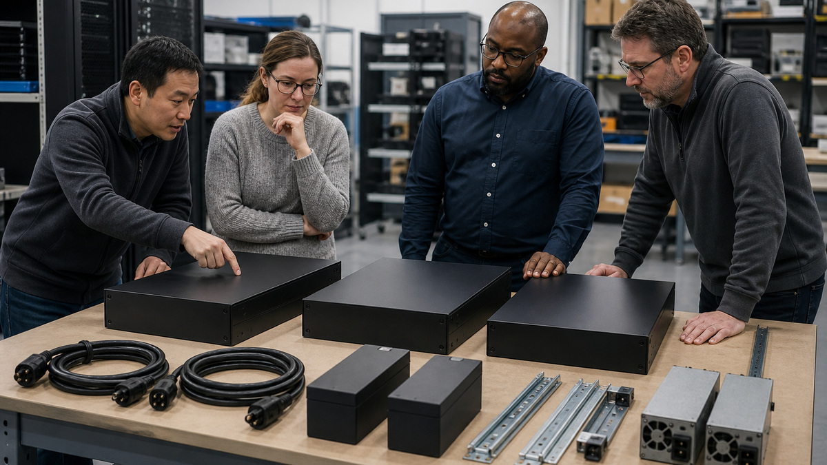
Use standby units for appropriate low-risk endpoint loads, line-interactive systems where Automatic Voltage Regulation can correct common voltage variation without consuming the battery, and online double-conversion systems where continuous conditioning, zero transfer time or difficult input power justifies the additional heat and cost. CyberPower’s product selector distinguishes these families, but the final choice must be verified against the exact model page and installation manual.
Match waveform to the protected equipment. CyberPower’s Smart App Sinewave models publish sine-wave output and Active PFC compatibility. Smart App LCD models may use simulated sine-wave output and are positioned for equipment capable of using it. Do not infer compatibility from connector shape. Check server, storage, telecom and power-supply requirements, especially for sensitive systems, active-PFC supplies or equipment that behaved poorly on a previous UPS.
Compare useful features rather than collecting checkboxes: rack or tower form, watt and VA rating, input plug, receptacles, line-interactive or online behavior, battery cartridge, extended battery module support, recharge time, hot-swap designation, network-card compatibility, USB or serial management, outlet control, EPO, generator mode and warranty. Document the chosen model and approved substitute because two CyberPower units with similar capacity can differ materially in waveform, runtime and management.
- Select topology from power quality, availability and transfer-time needs.
- Confirm waveform compatibility with the exact protected power supplies.
- Compare watt rating as well as VA rating for every candidate.
- Verify plug, outlets, rack form, EBM, EPO and management options.
- Define an approved substitute list that preserves every required capability.
Calculate Runtime at Real Load and Preserve Aging Margin

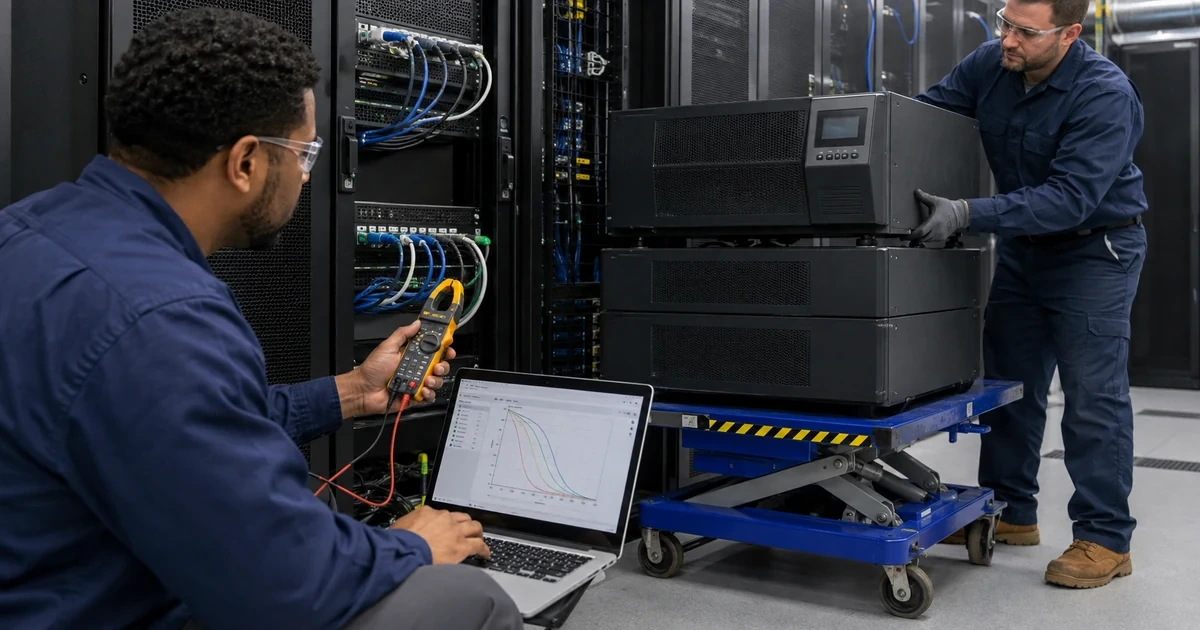
Use the measured watt load in CyberPower’s runtime calculator or the exact model’s runtime curve. Half-load and full-load headline figures are orientation points, not a prediction for a unique rack. Include devices that may be added before the next refresh, and confirm that the UPS watt limit is not exceeded even when VA appears acceptable. Preserve margin for startup demand, battery temperature, recharge state and normal capacity loss over time.
Work backward from the outage objective. Add detection delay, alert delivery, human decision time when applicable, application stop time, virtual-machine sequencing, host shutdown, storage destage and a safety reserve. If a generator is involved, include its start, stabilization and transfer behavior plus a plan for failed start. Extended battery modules can lengthen runtime on supported CyberPower models, but they also change space, weight, cabling, recharge and maintenance requirements.
Create a runtime acceptance target in minutes at a recorded load and battery condition. Commissioning should capture input, output, load percentage, battery charge, estimated runtime and actual observed performance during a controlled test. That baseline makes later degradation visible. Without it, a five-minute decline may be a failing battery, a larger rack load or a changed shutdown policy, and the team will not know which.
- Use the exact model runtime curve at measured watts.
- Include every shutdown stage and an explicit safety reserve.
- Allow for load growth, battery aging and incomplete recharge.
- Treat extended battery modules as maintained rack assets.
- Store measured commissioning runtime with the corresponding load map.
Validate Circuit, Rack, Ventilation, Grounding, and Service Access
Confirm the branch circuit, breaker, receptacle, input plug and voltage before the equipment arrives. A larger UPS may require a different receptacle or hardwired work by qualified electrical personnel. Keep the UPS directly connected as its manual requires, do not improvise with overloaded strips, household extension cords or undocumented adapters. Record which panel and breaker feed the unit and whether a second power path is genuinely independent.
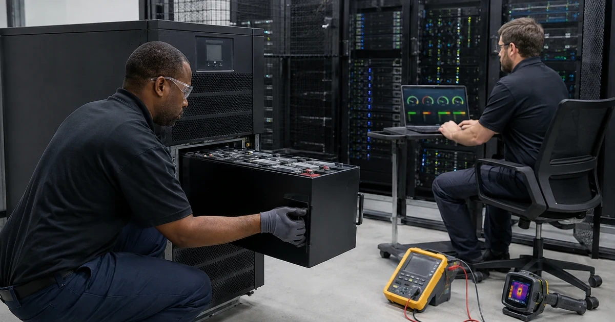
Plan rack position from actual weight, center of gravity, rail support and battery service. UPS and battery modules are usually among the heaviest rack components. Use the specified rail kit and sufficient personnel or lifting equipment, keep ventilation clear and preserve front and rear access. Verify ambient temperature and moisture limits because heat accelerates battery wear and cramped closets can invalidate an otherwise sound runtime plan.
Route input, output, USB or serial, network management, EPO and environmental sensor cables so service work cannot disconnect the wrong load. Mark protected and surge-only outlets in the as-built record without covering factory safety information. If EPO or a maintenance bypass is required, have qualified personnel design and test it against the exact model. A bypass is an operational control with failure modes, not a convenience cord.
- Verify circuit, voltage, plug and receptacle with facilities staff.
- Mount heavy UPS equipment on approved rails with safe lifting practice.
- Maintain airflow, temperature and service clearance.
- Document every protected outlet and dual-cord power path.
- Test EPO or bypass controls only under an approved safety procedure.
Build Outlet Groups, Monitoring, and Graceful Shutdown Together
Assign each plug to an outlet and business role before energizing the rack. Where the chosen CyberPower unit offers controlled banks, reserve the longest-running group for the firewall, management switch, carrier device and systems needed to coordinate shutdown. Put noncritical displays, lab equipment or secondary loads in an earlier shed group. Verify that remotely cycling a bank cannot remove power from both sides of a redundant device.
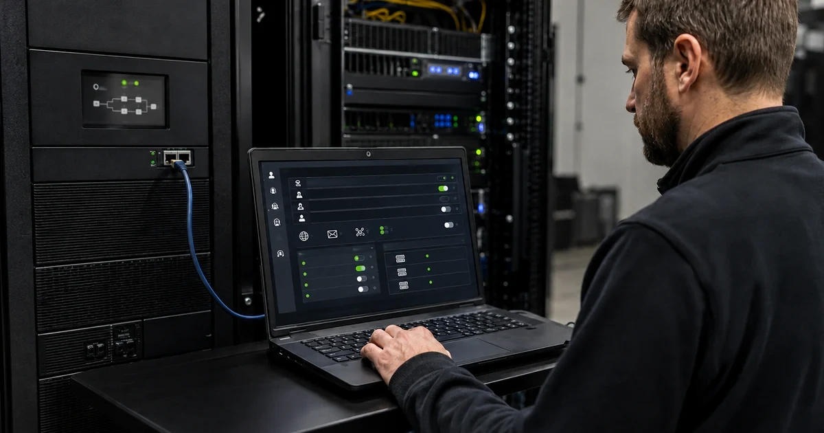
Choose local USB or serial management for a directly attached system, or an approved network-management design using PowerPanel Business and a compatible RMCARD where centralized visibility or multi-system shutdown is required. Name the owner for alerts, software updates, card firmware, configuration backup, credentials, certificates, time synchronization and log retention. Monitoring that nobody owns is only a delayed alarm.
Build shutdown policy from measured runtime thresholds and event duration, not a copied default. Coordinate application, virtual-machine, host, storage and network dependencies, then decide which services restart automatically and which require validation. Keep enough network and name-resolution capacity online for remote agents to receive the shutdown command. Test communication loss separately from a utility outage so a broken USB cable or unreachable RMCARD cannot silently defeat protection.
- Map each outlet to device, priority, shutdown stage and owner.
- Prevent one controlled bank from defeating redundant power design.
- Choose local or network management from the required shutdown scope.
- Assign ownership for alerts, credentials, firmware, time and logs.
- Test both power-loss and management-communication failure paths.
Commission with a Controlled Outage and Publish the Power As-Built
Before production cutover, inspect shipping condition, connect batteries as directed, allow the required charge interval and verify the LCD or management state. Confirm model, firmware context, battery cartridge, input and output, load, charge, alarms, controlled-bank mapping and connected management path. Test alerts to real recipients and make sure a warning identifies the correct site and UPS rather than a generic device name.
Run a controlled outage test during an approved window. Preserve application and infrastructure monitoring while removing utility input using the safe method for the installation. Observe transfer behavior, generator interaction where applicable, load, estimated runtime, actual runtime, alert timing, outlet-bank actions and graceful shutdown order. Restore input before the safety reserve is consumed and verify stable recharge, service recovery and cleared alarms.
Publish the final record: exact CyberPower model, protected equipment, measured watts and VA, circuit, receptacle, outlet map, battery and EBM details, management method, PowerPanel and RMCARD versions, alert owners, shutdown thresholds, test evidence, replacement cartridge, warranty, install date and next drill. ALLMSP can maintain this record through battery changes, rack additions and generator exercises so runtime remains a managed control rather than a hopeful estimate.
- Verify charge, load, alarms, management and alert delivery before cutover.
- Exercise transfer and shutdown under a controlled maintenance plan.
- Compare observed runtime with the documented acceptance target.
- Confirm clean recharge and application recovery after input returns.
- Store an owned power as-built and schedule its next review and drill.
Official product documentation and ALLMSP resources
- CyberPower UPS Product Selector
- CyberPower Smart App Sinewave UPS Systems
- CyberPower Smart App Online OL1KRTHD
- CyberPower PR1500RM1UC Product Details
- CyberPower UPS Runtime Calculator
- ALLMSP CyberPower Hardware Support
- ALLMSP Hardware Support
- ALLMSP Managed IT Services
- ALLMSP Cybersecurity Services
- ALLMSP Network Security
- Contact ALLMSP
Frequently Asked Questions
Should a CyberPower UPS be sized from VA or watts?
Use both, but the connected watt load and the UPS watt limit are essential. Measure the real rack, confirm VA and power-factor context, and keep margin below both ratings.
When is a CyberPower sine-wave UPS important?
Sine-wave output is appropriate when protected equipment or Active PFC power supplies require it. Verify the exact equipment and model rather than assuming simulated output is compatible.
What is the difference between line-interactive and online double-conversion UPS topology?
Line-interactive units use voltage regulation and transfer to battery for some events, online double-conversion units continuously produce conditioned output and can provide zero transfer time on supported models.
How much CyberPower UPS runtime should a server rack have?
Enough for detection, alerting, the complete shutdown or generator-transfer sequence, and a safety reserve at the measured watt load, with margin for aging and growth.
Can a half-load runtime figure predict an exact rack's runtime?
No. Use the exact CyberPower model’s runtime curve or calculator at measured watts and validate it with a controlled commissioning test.
Should both power supplies of a server connect to one UPS?
Only if that matches the intentional failure-domain design. Many environments should distribute redundant supplies across genuinely independent supported power paths.
Where should a rackmount CyberPower UPS be installed?
Place it on approved rails in a location that supports its weight, airflow, cable routing and battery service, usually low in the rack according to the rack and UPS instructions.
Can a CyberPower UPS be connected through an ordinary extension cord or power strip?
Do not improvise. Follow the exact UPS installation manual and have facilities provide the correct circuit, receptacle and input connection.
Why map CyberPower controlled outlet banks?
A verified outlet map lets noncritical loads shut down first while preserving network, storage and management systems, and prevents a remote cycle from cutting both sides of redundant equipment.
How can ALLMSP help deploy CyberPower UPS systems?
ALLMSP can measure load, select topology and runtime, coordinate circuits and racks, configure monitoring and shutdown, run controlled tests, and maintain the lifecycle record.