























































































































































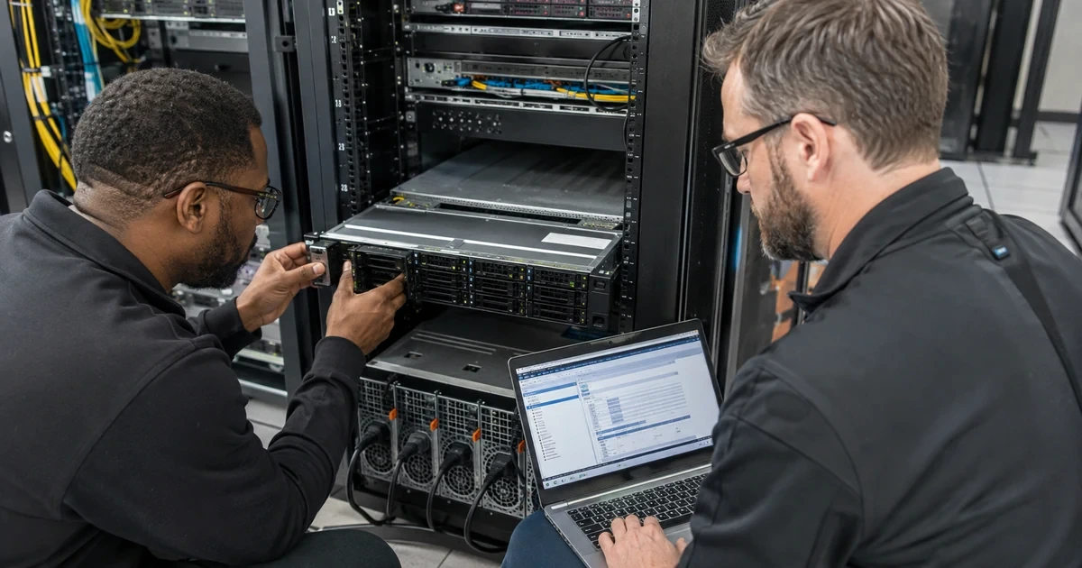
A new Dell PowerEdge server can pass POST and still be poorly deployed. Memory may be populated in a suboptimal pattern, both power supplies can land on one circuit, a PERC virtual disk may not match recovery objectives, or iDRAC may be reachable only through an installer’s undocumented address. These gaps surface during failure, when the maintenance window has already disappeared.
Dell’s current PowerEdge service manuals document chassis-specific rails, weight, memory, storage controllers, drives, risers, power supplies, cooling and minimum configurations. iDRAC10 adds out-of-band inventory, remote console, signed updates, role-based access and Lifecycle Controller functions. OpenManage Enterprise can compare discovered servers with Dell catalog baselines, but remediation is an initiated maintenance action rather than automatic compliance.
This plan connects application requirements to the physical server, out-of-band management, storage layout, firmware state and recovery evidence. ALLMSP can maintain the resulting build standard as hardware revisions, firmware and workloads change instead of treating commissioning as a one-time installation task.
When an organization in Lawrenceville, Suwanee, Gwinnett County, Metro Atlanta, or elsewhere in Georgia needs to deploy Dell PowerEdge servers with iDRAC, Lifecycle Controller, and RAID, ALLMSP handles the work in house from initial review through validation and ongoing support.
Key decisions at a glance
- Size the exact PowerEdge chassis from workload, memory population, storage, PCIe, network, accelerator, power, cooling and serviceability requirements rather than CPU count alone.
- Design dedicated iDRAC access, naming, time, identity and recovery before the operating system is installed.
- Choose PERC, BOSS, direct-attached or software-defined storage deliberately, document RAID, hot-spare, cache, boot and replacement behavior.
- Use Lifecycle Controller and Dell-provided catalogs to inventory, stage and verify a model-appropriate firmware baseline in a maintenance window.
- Commission redundancy, alerts, diagnostics, backup, restore and workload failover, then deliver an as-built record another technician can operate.
Translate Workload Requirements into the Exact PowerEdge Configuration

Document the services, virtualization role, database or application profile, CPU behavior, memory working set, storage IOPS and latency, network throughput, recovery objective, maintenance tolerance and expected growth. Select rack, tower or modular form from site and support requirements. For each candidate, verify processor sockets, memory channels and capacity, drive backplane, PERC or HBA options, BOSS boot, PCIe and OCP slots, GPU support, network ports, power supplies and warranty from the exact Dell configuration and service manual.
Plan compatible population rather than isolated components. Memory speed and capacity depend on supported DIMM types and slot rules, riser choices can consume accelerator or network options, certain drives require a matching backplane and controller, added PCIe devices can change airflow and fan behavior. Record the approved bill of materials and substitutes so later expansion preserves balanced memory, storage protection, cooling and supportability.
Reconcile the final Dell quote and factory configuration with the design before shipment. Record component identifiers and warranty coverage without publishing sensitive Service Tag details. A procurement substitution that changes the backplane, PERC, riser, network adapter or power supply can alter installation, firmware and recovery procedures even when the chassis name remains the same.
- Capture workload, growth, recovery and maintenance targets.
- Validate the exact chassis, backplane, riser and power options.
- Use Dell memory-population and component-compatibility rules.
- Reserve capacity for monitoring, backups and failure operation.
- Publish an approved configuration and substitute list.
Prepare Rack, Power, Cooling, Cabling, and Service Access
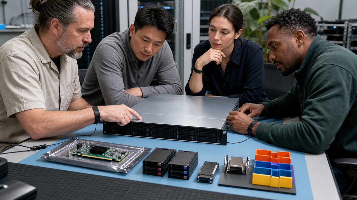
Confirm rack depth, rail compatibility, cable-management arm, equipment weight, lifting plan and front-to-rear airflow before delivery. Preserve service clearance for drive, fan, power-supply and motherboard work. Use blanking panels and a rack airflow plan rather than allowing hot exhaust to recirculate. Measure inlet conditions and compare them with the model’s environmental limits, the room set point does not prove the server intake is acceptable.
Map each power supply to an independent UPS, PDU and branch circuit where the availability design requires it. Size circuits for the planned load and startup behavior, then document receptacles and PDU outlets. Route production, storage and iDRAC cabling separately with labels in the as-built record, redundant paths where applicable and enough slack for service without blocking airflow or disconnecting a neighboring system.
Coordinate facilities, network and server ownership before the maintenance window. Confirm grounding, rack stability, PDU capacity, emergency shutdown expectations and environmental monitoring. Stage the correct rails, fasteners, transceivers and cable lengths so installers do not improvise load-bearing hardware, power adapters or unsupported optics during the cutover.
- Verify rails, weight, rack depth and safe lifting resources.
- Maintain correct airflow, inlet monitoring and service clearance.
- Land redundant supplies on genuinely independent power paths.
- Separate management, production and storage cabling.
- Record rack unit, PDU outlet, circuit and switch port assignments.
Establish iDRAC and Lifecycle Controller as the Recovery Plane
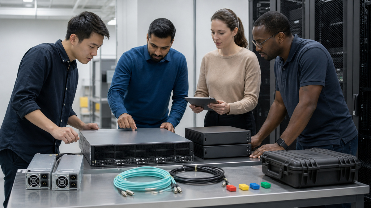
Connect the dedicated iDRAC interface where the model and license support it, or document the selected shared-port behavior. Assign the approved address, DNS name, time source, certificate plan and management VLAN before host networking. Place credentials and recovery ownership in the organization’s vault. Test access from the supported jump path and verify that the management network remains available when the host operating system is stopped.
Inventory the factory state through iDRAC and Lifecycle Controller: Service Tag context, BIOS, iDRAC, CPLD, PERC, backplane, NIC, PSU, drives and other component firmware. Export the initial inventory and configuration before making changes. Confirm boot mode, system profile, virtualization features, secure boot requirements, console, virtual media and serial settings against the deployment standard rather than inheriting unknown defaults.
Exercise a local and remote recovery before workload installation. Verify virtual console and approved virtual media, then confirm an authorized technician can reach Lifecycle Controller when the host network and boot volume are unavailable. Record license-dependent features and the fallback method so an emergency does not begin with a search for an unknown credential or cable.
- Give iDRAC a durable name, address, time source and owner.
- Test out-of-band access independently of the host OS.
- Capture factory component and firmware inventory.
- Set BIOS and Lifecycle Controller options from an approved standard.
- Preserve a local recovery method for management-network failure.
Design PERC, Boot, RAID, and Disk Replacement Behavior
Choose between PERC hardware RAID, HBA, direct NVMe, BOSS boot or software-defined storage from the platform and application design. Define virtual disks, RAID level, stripe and cache policy, hot spares, disk encryption, controller protection and rebuild expectations using supported Dell components. RAID improves availability for selected failures but does not replace application-consistent backup, replication or tested restore.
Separate boot from data where appropriate and record controller, enclosure, slot and drive serial context. Model usable capacity, rebuild exposure, endurance and failure performance. Decide exactly what an operator does for a predicted failure, failed disk, foreign configuration, degraded virtual disk or controller alert. Pre-stage supported replacement procedures without assuming every carrier or NVMe device is hot-swappable in every backplane.
- Select controller and RAID behavior from workload and recovery needs.
- Document drive-to-bay and virtual-disk mapping.
- Preserve supported hot-spare and rebuild headroom.
- Keep tested backups outside the RAID failure domain.
- Write model-specific replacement and escalation steps.
Create a Dell Firmware Baseline and Deploy the Operating System
Use Dell-provided catalogs or exact-model packages to define the intended BIOS, iDRAC, CPLD, PERC, NIC, drive, backplane and PSU state. OpenManage Enterprise documentation describes catalog-backed baselines and compliance reports, while noting that updates are initiated and may require staged reboots or cold cycles. Review prerequisites and dependencies, export current configuration, maintain stable power and update in a tested order during an approved window.
After firmware, refresh inventory and prove compliance rather than trusting a completed job. Use Lifecycle Controller or the approved automation platform to deploy the supported operating system, drivers and boot configuration. Join the host to monitoring, backup, identity and patching services only after hostname, time, network, storage multipathing, security controls and recovery access match the build record.
- Build the baseline from official Dell catalogs or exact-model packages.
- Stage updates with power, backup, dependency and reboot planning.
- Refresh inventory and compliance after each maintenance stage.
- Deploy a supported OS and driver set through an owned workflow.
- Enroll monitoring, backup and patching after platform acceptance.
Commission Failure Paths and Publish the PowerEdge As-Built
Validate POST, boot, iDRAC, virtual console, time, inventory, PERC health, disk status, memory, NICs, redundant links, power supplies, fans and sensors. Exercise one power path, one network path and a controlled host restart without defeating redundancy. Run Dell embedded diagnostics where appropriate, create a SupportAssist Collection baseline and confirm alerts reach the correct team with the correct server identity.
Test workload backup, restore and failover rather than stopping at hardware health. Export the accepted BIOS, iDRAC and storage configuration and record model, Service Tag context, warranty, rack, power, switches, addresses, firmware, storage map, spare parts, alert owners and maintenance windows. ALLMSP can use that evidence to control expansion and make the next hardware event an expected procedure instead of a discovery exercise.
- Verify every component and sensor after the final reboot.
- Test redundant power, network and recovery paths safely.
- Create baseline diagnostics and SupportAssist evidence.
- Prove application backup and restore at the deployed state.
- Deliver configuration exports and an owned lifecycle register.
Official product documentation and ALLMSP resources
- Dell PowerEdge R760 Initial Setup and Configuration
- Dell PowerEdge R760 System Overview
- Dell iDRAC10 Key Features
- Dell OpenManage Enterprise 4.7 Firmware Management
- Dell PowerEdge R760 Installation and Service Manual
- ALLMSP Dell Hardware Support
- ALLMSP Hardware Support
- ALLMSP Managed IT Services
- ALLMSP Cybersecurity Services
- ALLMSP Network Security
- Contact ALLMSP
Frequently Asked Questions
What should be sized before choosing a Dell PowerEdge model?
Size the workload, memory population, storage IOPS and capacity, PCIe and network needs, accelerators, power, cooling, rack constraints, recovery objective and expected growth.
Why should iDRAC be configured before the operating system?
iDRAC is the out-of-band recovery plane. Its address, name, time, certificate, identity and network path should be testable even when the host OS is unavailable.
Does RAID replace backup on a PowerEdge server?
No. PERC RAID can preserve service through selected disk failures, but application-consistent backup, replication and tested restore address different failure modes.
What should a Dell firmware baseline include?
Include applicable BIOS, iDRAC, CPLD, PERC, backplane, NIC, drive, PSU and other component firmware from an official Dell catalog or exact-model packages.
Does OpenManage Enterprise automatically fix noncompliant firmware?
No. Dell documents baseline comparison and initiated remediation, administrators must plan privileges, dependencies, maintenance windows and required reboots.
What is Lifecycle Controller used for?
Lifecycle Controller supports out-of-band inventory, configuration, deployment, diagnostics and firmware workflows without depending entirely on the installed host operating system.
How should redundant PowerEdge power supplies be connected?
Where availability requires it, place them on genuinely independent UPS, PDU and branch-circuit paths and record the exact outlet and circuit mapping.
What should be tested before a PowerEdge server enters production?
Verify POST, boot, iDRAC, storage, memory, NICs, power, fans, sensors, alerts, diagnostics, configuration backups and the workload’s restore or failover procedure.
What belongs in a PowerEdge as-built record?
Record model, Service Tag context, warranty, rack, power, switches, addresses, versions, storage layout, configuration exports, alerts, spares, maintenance windows and owners.
How can ALLMSP deploy Dell PowerEdge servers?
ALLMSP can validate the design, stage iDRAC and firmware, configure storage, coordinate OS deployment, test failure paths and maintain the lifecycle evidence.