

















































































































































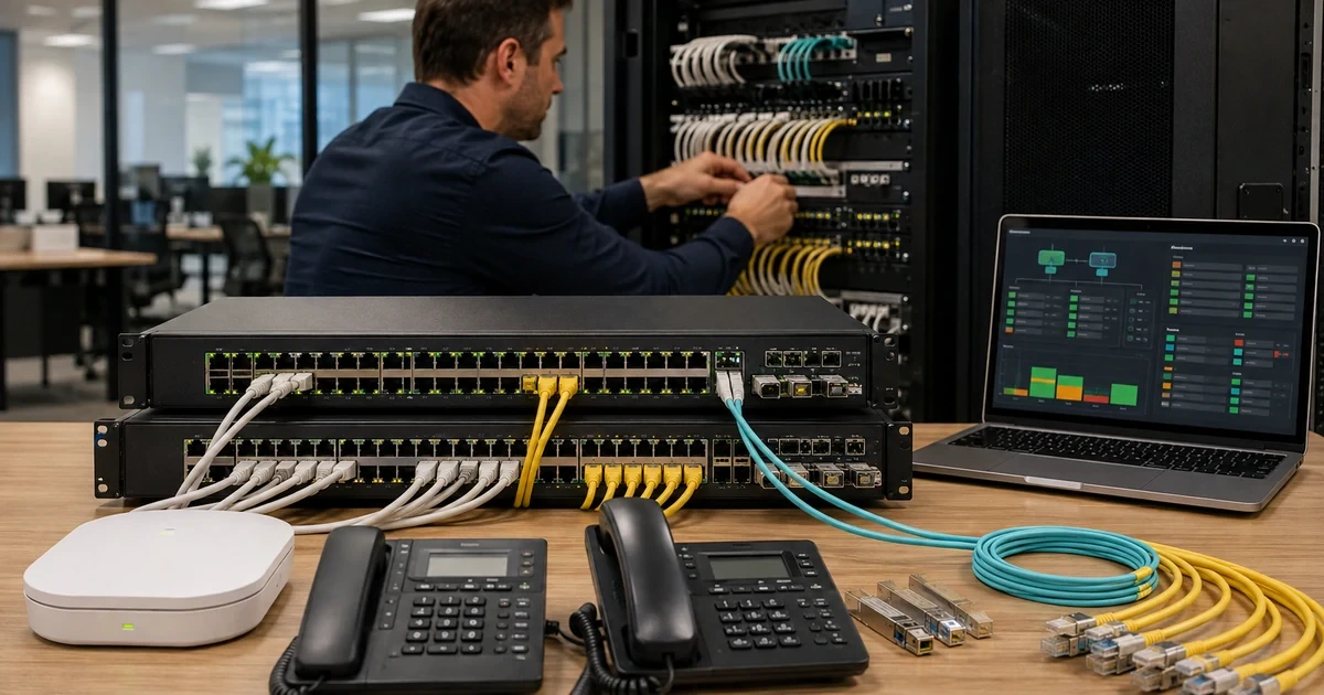
A healthy AOS-CX stack can hide a dangerous operating condition. One member may have the wrong number, a chain may have no redundant path, split detection may be absent, a power-supply failure may leave no PoE headroom for access points, or Central may report a local override that nobody owns. The switch continues forwarding until an ordinary maintenance action exposes the design debt.
Aruba documents VSF for supported 4100i, 6100, 6200, and 6300 series, with model-specific member limits and link rules. Current 10.16 guidance recommends ring topologies when feasible because a chain has only one path between members. AOS-CX also provides configuration checkpoints and rollback, while Central exposes configuration status, pending changes, local overrides, monitoring, alerts, and audit trail. These controls must be combined with physical topology and power records.
This article intentionally omits production IP addresses, VLAN names, credentials, RADIUS secrets, SNMP communities, API tokens, configuration dumps, serial numbers, transceiver identifiers, and detailed rack maps. Store exact values in the controlled network record. The public-safe goal is to show a repeatable method for resilient switching, powered-device continuity, reversible change, and verified recovery.
For organizations in Lawrenceville, Suwanee, Gwinnett County, Metro Atlanta, and across Georgia, ALLMSP can operate Aruba AOS-CX switches with VSF, PoE, and checkpoints through one accountable in-house process for assessment, configuration, testing, and support.
Key decisions at a glance
- Inventory AOS-CX platform, software, serial, stack identity, member, role, VSF links, split detection, uplinks, transceivers, power supplies, fans, PoE, connected critical devices, Central state, and support entitlement.
- Use only model-supported VSF membership and link combinations, prefer resilient topologies where Aruba recommends them, and plan conductor, standby, member numbering, cabling, and split behavior before installation.
- Budget PoE by actual powered-device class and criticality, including AP boot peaks, phones, cameras, sensors, failure headroom, power-supply loss, and any always-on or quick-PoE behavior supported by the exact platform.
- Name one source of configuration authority, review Central pending changes and local overrides, create and validate checkpoints, and define an out-of-band recovery route before high-risk change.
- Stage firmware and replacement by model, stack topology, transceiver, feature, and site dependency, verify forwarding, VSF, uplinks, PoE, endpoints, configuration synchronization, and alerts after every step.
Inventory AOS-CX Hardware, Configuration Authority, and Dependencies

Build a device record before changing a switch or stack. Capture series and exact model, serial and asset tag, AOS-CX version and image bank, Central workspace, application, subscription, group and site, configuration mode, configuration-sync status, local overrides, management and console paths, support entitlement, rack and power source, power-supply and fan inventory, transceivers and supported status, uplinks and LAGs, spanning-tree or routing role, VLAN and policy ownership, authentication dependencies, VSF or VSX role, member numbers, conductor and standby, split-detection method, stack link ports and speeds, PoE capacity and consumption, UPS runtime, critical powered devices, monitoring, backup and checkpoint state, spare, and operational owner. Protect all sensitive values. Define configuration authority explicitly. Aruba Central can be the source of configuration for a managed AOS-CX switch, UI groups, templates, MultiEdit, local CLI, automation, and emergency console access should not become competing writers. Record which method owns common settings, how variables are reviewed, whether auto commit is enabled, who may create a local override, and how Central reconciliation occurs after an emergency. Review the Configuration Status page for synchronized, pending, offline, conflict, login, unsupported firmware, modified-outside-Central, and local-override conditions. A switch that forwards traffic while Central cannot authenticate or read state is not operationally complete. Use the audit trail to prove onboarding, configuration push, and subsequent administrative events. Map dependencies by service rather than port count alone. Identify access points, phones, cameras, door systems, sensors, uplinks, identity services, DHCP, DNS, management collectors, out-of-band access, and business processes affected by each member. Link the logical diagram to rack elevation, patch panel, cable IDs, power circuits, UPS, and spare location. Verify redundant links do not share an accidental common failure such as one patch panel, conduit, power supply, or upstream chassis. Establish baselines for interface errors, utilization, transceiver health, temperatures, fans, power supplies, CPU, memory, event rate, VSF state, PoE draw, and endpoint count. Alert thresholds should distinguish short transition from persistent impact and route to an owner who can reach the site. Review unused accounts, remote protocols, certificates, time, logging, authentication, and secure management against the current AOS-CX hardening guidance for the platform. Inventory closes only when Central, switch, diagram, rack, cable, power, and service-owner records agree.
- Record exact platform, software, Central state, configuration authority, overrides, support, rack, power, transceivers, uplinks, roles, VSF, PoE, UPS, dependencies, checkpoints, spare, monitoring, and owner.
- Prevent UI, template, CLI, and automation from becoming competing writers.
- Reconcile Central configuration and audit state with the live switch.
- Map service and physical common-mode failures.
- Baseline forwarding, hardware, stack, power, and endpoint health.
Design and Validate VSF Membership, Links, and Failure Behavior
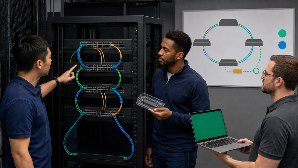
Confirm that every proposed member and software version supports the intended VSF design. Current AOS-CX 10.16 documentation covers 4100i, 6100, 6200, and 6300 series with different limits, port capabilities, and mixing rules. Do not infer that two similar front panels can join the same stack. Record the exact SKU, member limit, supported link speed and port, allowed model combinations, cable and optic support, and minimum common software. Plan member numbering before installation because renumbering causes a reboot and clears configuration on the renumbered switch, a non-primary member may not boot fully without conductor reachability. Label chassis, member, link, direction, rack unit, power feed, and uplink before connecting production endpoints. Choose conductor and standby deliberately. Place them on reliable hardware and distinct power where the design permits, and document how control-plane failover is tested. Build VSF links with consistent supported speed, short and traceable physical paths, and enough bandwidth for the failure state. Aruba recommends a ring where feasible because a single link or member failure does not isolate the remaining stack, while a chain has only one path. When the platform or size uses a chain, document split risk and configure the supported split-detection design. Keep split-detection traffic independent enough to reveal a stack partition rather than fail with the same cable bundle. Validate the out-of-band or serial-console path to more than the conductor. Stage members off production. Verify erased or known state, approved firmware, member ID, VSF link definitions, priority or role, split detection, and link health. Add one member at a time and compare discovered model, member, topology, software, configuration, interfaces, and PoE. Do not connect user-facing ports until the expected member identity and port mapping are proven. Test controlled failures in an approved window: one VSF link, one nonconductor member, standby takeover, conductor loss, upstream LAG member, power supply, and monitoring path. Observe forwarding, control-plane role, link reconvergence, endpoints, PoE continuity, alerts, and recovery. Stop if the test creates duplicate gateways, loops, split stack, wrong port numbering, unexpected reboot, or loss outside the planned boundary. Maintain a replacement runbook with compatible SKU, software, member ID, stack link, configuration source, transceivers, power supplies, rack plan, console access, and rollback. A spare that has never been booted, licensed, versioned, or cabled in a lab is a purchasing record, not a recovery capability.
- Verify exact series, SKU, software, member limits, model mixing, link ports, speeds, optics, and topology from current guidance.
- Plan member IDs because renumbering reboots and clears the member configuration.
- Prefer a resilient ring where feasible and engineer split detection for chain risk.
- Add and validate members one at a time before endpoints.
- Test link, member, conductor, standby, uplink, power, alert, and replacement behavior in a controlled window.
Engineer PoE Capacity, Endpoint Priority, and Power Recovery
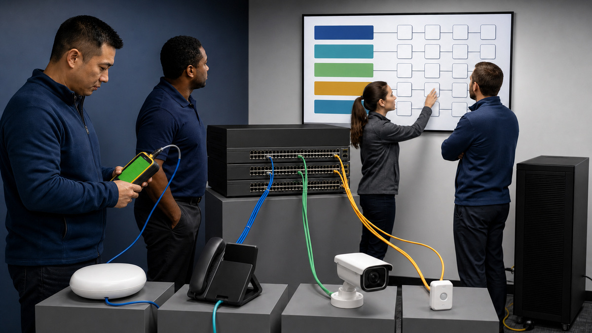
Inventory every powered endpoint by switch, member, port, type, model, requested and observed power, IEEE class, operational mode, business criticality, alternate power, boot behavior, and owner. Access points may request more power as additional radios or features activate, cameras may draw more with heaters or infrared illumination, phones may power attached devices. Use measured values for trending but size from supported maximums and real failure scenarios. Calculate budget at port, line card or subsystem, member, chassis, power supply, and UPS levels as the platform requires. Include startup surge, simultaneous reboot, future devices, feature enablement, ambient conditions, and loss of one power supply or stack member. Document which loads remain powered during a reduced-capacity state. A total below the nominal wattage is not proof of resilience. Set PoE priority according to business continuity and safety policy. Critical network APs, emergency phones, physical security, clinical or operational sensors, and ordinary convenience devices may need different treatment, but priority must reflect an approved service model rather than a technician’s guess. Avoid port descriptions that expose sensitive physical-security or executive locations in broadly accessible systems. Monitor denied power, overload, utilization, classification mismatch, port cycling, link flaps, and powered-device restarts. Aruba Central offers AOS-CX PoE utilization alerts on supported platforms and versions, validate availability for the exact series and firmware. Correlate the alert with switch event logs and endpoint behavior rather than repeatedly bouncing the port. Treat always-on PoE and quick-PoE as platform-specific features with tradeoffs. Confirm current model support, required configuration, saved state, oversubscription constraints, security impact, and endpoint behavior before enabling them. Fast power restoration is useful only if the switching, VLAN, authentication, DHCP, and upstream path also recover correctly. Test a controlled switch reboot, power-supply loss, member loss, and UPS transition with representative AP, phone, and camera loads. Observe whether powered devices reboot, whether ports restore expected power and link, how long identity and network services take to return, and whether any endpoint enters a degraded power mode. Define manual load-shedding and restoration order for an extended power event. Keep electrician work and energized-hardware procedures within qualified roles. Close a PoE incident by identifying cable, endpoint, power supply, thermal, configuration, budget, or platform cause, verifying stable power and network service, updating capacity forecast, and checking similar ports. Recurrent reboots are a fleet signal, not a reason to add an automatic port-cycle loop.
- Inventory endpoint class, requested and observed power, maximum, criticality, alternate source, boot, and owner.
- Size port, member, chassis, supply, and UPS capacity for startup, growth, feature use, and single failures.
- Approve load priority and reduced-capacity behavior.
- Validate support before using always-on or quick-PoE features.
- Test reboot, supply, member, and UPS transitions with real endpoint types and resolve causes rather than automating resets.
Use Checkpoints, Stage Firmware, and Recover AOS-CX Safely
Classify each change by blast radius and reversibility. A port description differs from a stack-link, spanning-tree, routing, authentication, VLAN-pruning, firmware, or management-path change. Build the change package with current running and startup state, Central configuration and pending diff, approved target, dependency and endpoint map, checkpoint, console path, test plan, stop conditions, rollback command or configuration, firmware image and integrity source, spare readiness, maintenance window, communications, and authorized engineers. AOS-CX checkpoints are snapshots of running configuration and metadata. Create a named user checkpoint immediately before the work, inspect the difference, and ensure the checkpoint exists on the intended switch. Checkpoint auto mode can provide a timed safety mechanism on supported workflows, but it is not a substitute for understanding whether rollback will restore remote reachability or reverse external changes. Test checkpoint creation and rollback on representative lab hardware and current software. Never assume a configuration rollback can undo a firmware defect, endpoint state, upstream change, or physical cabling error. If Central is authoritative, reconcile the restored switch with Central so an old pending change does not reapply the fault. Stage firmware by exact platform, stack composition, feature use, transceivers, Central support, release notes, security need, and business calendar. Verify supported upgrade path and image bank behavior. Start with lab and a representative low-risk stack, then move through production rings. Before reboot, confirm VSF health, conductor and standby, links, split detection, uplinks, power supplies, flash, checkpoint and startup configuration, Central reachability, local console, endpoint impact, neighboring wireless coverage, identity and DHCP availability, and vendor support. Observe each member’s image, boot, stack rejoin, role, interfaces, LAGs, spanning tree or routing, authentication, PoE, powered endpoints, transceivers, alerts, and configuration sync. Do not declare success from a version string alone. For failure, preserve event logs and support data before destructive recovery where possible. Use the current platform’s console, ServiceOS, rollback, alternate image, member replacement, or vendor-support path. Stop if identity, loop prevention, routing, stack state, or powered critical service is uncertain. After change, compare running, startup, checkpoint, Central, and intended configuration, confirm local overrides and pending changes, verify baseline metrics and service-owner tests, remove temporary access, and update diagrams, port and power records, spare images, and knowledge. A controlled operation ends when configuration authority, switch state, physical topology, endpoints, monitoring, and documentation converge again.
- Package current and target configuration, Central diff, checkpoint, console, dependencies, tests, stops, rollback, image, spare, window, and owners.
- Create and inspect an AOS-CX checkpoint before risky change and understand what it cannot reverse.
- Stage firmware by exact platform and topology.
- Verify stack, forwarding, authentication, PoE, endpoints, hardware, alerts, and configuration sync after reboot.
- Preserve evidence and use current supported recovery paths when a switch fails to return.
Official product documentation and ALLMSP resources
- HPE Aruba Networking Central: Getting Started with AOS-CX Deployments
- HPE Aruba Networking Central: AOS-CX Configuration Status
- HPE Aruba Networking: AOS-CX 10.16 VSF Guide
- HPE Aruba Networking: AOS-CX 10.16 VSF Connection Topology
- HPE Aruba Networking: AOS-CX 10.16 Checkpoint Commands
- ALLMSP Aruba Hardware Support
- ALLMSP Hardware Support
- ALLMSP IT Consulting
- ALLMSP Managed IT Services
- ALLMSP Cybersecurity Services
- Contact ALLMSP
Frequently Asked Questions
Which Aruba switches support VSF?
Current AOS-CX 10.16 VSF guidance covers supported 4100i, 6100, 6200, and 6300 series, with model-specific member limits, link ports, speeds, and mixing rules.
Why does VSF member numbering need planning?
Renumbering causes a reboot and clears configuration on the member. A non-primary member also depends on conductor reachability to boot normally.
Is an Aruba VSF ring better than a chain?
Aruba strongly recommends a ring where feasible because it provides another path after a single link or member failure. A chain has one path and greater split risk.
What should be tested after an AOS-CX conductor failover?
Verify the new role, management, forwarding, uplinks, LAGs, loop prevention, authentication, PoE, endpoints, alerts, configuration synchronization, and recovery of the former conductor.
How much PoE headroom should an Aruba switch retain?
Keep enough for endpoint maximums, startup, growth, feature activation, and the approved failure scenario such as one power-supply or member loss. The exact margin depends on platform and services.
What is an AOS-CX checkpoint?
It is a snapshot of the running configuration and relevant metadata that can be used for comparison or rollback. It does not reverse firmware, physical, endpoint, or upstream changes.
Can Central and the local CLI both manage an AOS-CX switch?
They can be used in controlled roles, but one authority must own intended state. Emergency local changes must be documented and reconciled with Central to prevent reapplication or drift.
What should be checked after AOS-CX firmware upgrades?
Check every member image and role, VSF links, uplinks, interfaces, routing or spanning tree, authentication, PoE, endpoints, transceivers, alerts, audit state, and Central synchronization.
What makes an Aruba spare switch usable?
It must be compatible, boot-tested, on an approved image, understood for member ID and links, supplied with correct optics and power, accessible by console, and included in a rehearsed replacement plan.
How can ALLMSP improve Aruba switching reliability?
ALLMSP can reconcile Central and physical state, validate VSF, forecast PoE, govern configuration and checkpoints, stage firmware, test failures, and maintain replacement readiness.