



























































































































































Structured cabling is the permanent foundation beneath computers, desk phones, wireless access points, cameras, printers, point-of-sale systems, conference rooms, building technology, and internet service. A good installation lets those systems change without reopening ceilings or guessing where a cable terminates. A poor installation can create intermittent failures, limited Power over Ethernet, slow links, crowded pathways, difficult moves, and years of avoidable troubleshooting.
The design should begin with work areas, devices, service expectations, floor plans, telecommunications rooms, backbone paths, future growth, and the network equipment that will use the links. Cable category alone does not define quality. Components, topology, pathway, length, bend radius, pulling tension, separation, termination, patching, testing, administration, grounding, firestopping, and workmanship all contribute to the finished channel.
ALLMSP designs and installs business data and voice cabling in house for Lawrenceville, Suwanee, Gwinnett County, Metro Atlanta, and projects throughout Georgia. We connect the physical installation to switching, Wi-Fi, VoIP, PoE, racks, cybersecurity, documentation, and user cutover so each outlet is ready for the service it is intended to support.
Plan the cable plant around spaces, services, and future change
- Survey demand: Count users, rooms, devices, wireless access points, phones, cameras, displays, printers, building systems, spares, and likely growth.
- Map spaces: Identify service entrances, equipment rooms, telecommunications rooms, backbone routes, horizontal pathways, work areas, and special environments.
- Select the media: Choose copper, fiber, connectors, pathway materials, patching, and enclosures for the supported applications and property conditions.
- Coordinate the network: Plan racks, panels, switches, PoE, uplinks, voice VLANs, Wi-Fi, internet handoff, power, cooling, security, and management.
- Define testing: Specify the link model, test limit, tester requirements, identifiers, result format, remediation process, and final acceptance.
- Prepare handoff: Require labels, as-built drawings, port maps, test results, photos, warranties, inventories, cutover records, and support ownership.
Design outlets, rooms, pathways, copper, fiber, and growth capacity
Walk each work area with the business and construction stakeholders. Record desk layouts, conference rooms, wall displays, reception, printers, wireless coverage plans, phones, cameras, access control, point-of-sale devices, production equipment, flexible seating, and future expansion. Decide which locations need multiple links, ceiling outlets, floor boxes, service loops, direct device connections, or fiber. Include spare capacity in pathways, racks, patch panels, and switches where growth is likely rather than treating every unused port as waste.
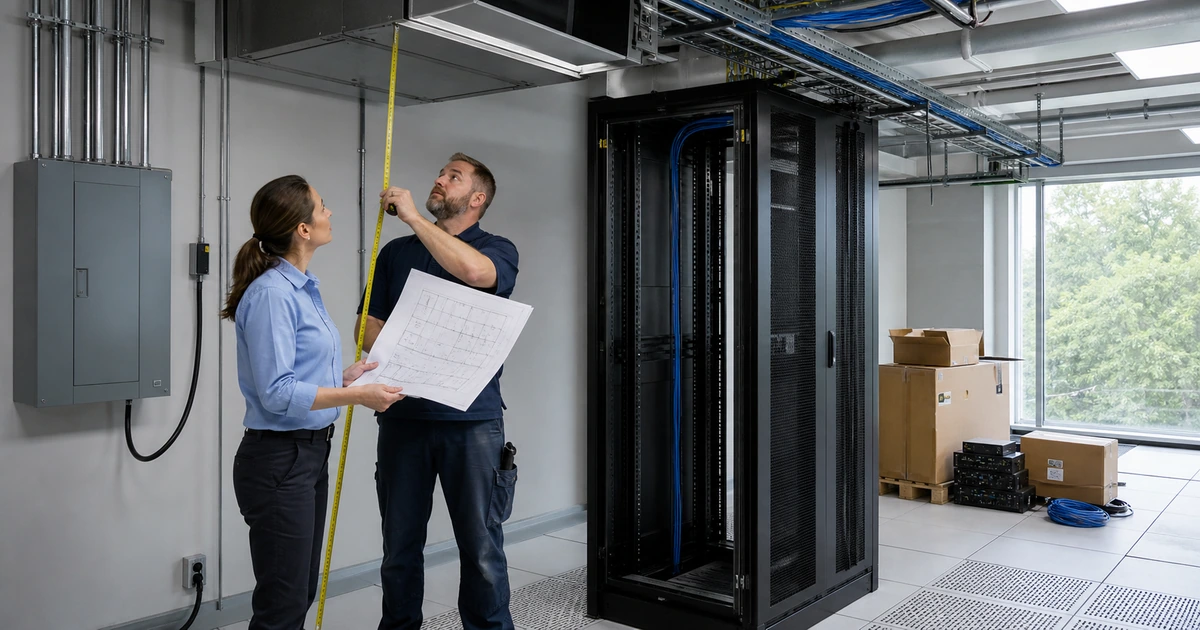
Choose telecommunications spaces that remain accessible, secure, dry, clean, ventilated, and close enough to serve the planned runs within the selected system limits. Avoid using a random electrical, janitorial, or storage room as the long-term network center. Coordinate dedicated power, backup power, grounding and bonding requirements, cooling, wall and rack clearance, sleeves, tray, conduit, fire-rated assemblies, and the route from the service entrance to equipment and floor distribution. Confirm property-specific permits, codes, licensing, firestopping, and building requirements with the responsible professionals before installation.
Select media and components as a complete supported system. Use copper for appropriate horizontal links and fiber where distance, bandwidth, electrical isolation, environment, or backbone design calls for it. Match cable, jacks, panels, cords, connectors, and test limits. Plan plenum, riser, outdoor, wet-location, armor, ultraviolet, industrial, and electromagnetic conditions correctly. TIA’s TR-42 committees maintain standards covering premises topology, design, installation, performance, administration, pathways, spaces, bonding, grounding, copper, and fiber, so the project specification should identify the applicable current requirements rather than relying on a vague statement such as install network cable.
- Work-area schedule: List each outlet, device, service, quantity, mounting location, furniture dependency, accessibility need, and spare requirement.
- Room plan: Define racks, panels, switches, uplinks, power, UPS, cooling, clearances, security, grounding, and service access.
- Pathway map: Coordinate sleeves, tray, conduit, supports, penetrations, firestopping, fill, future access, and route ownership.
- Media schedule: Specify supported application, copper or fiber type, components, environment, distance, connectors, and test limit.
- Growth reserve: Retain practical capacity in pathways, backbone strands, panels, rack units, switch ports, power, and cooling.
The physical design is ready when every planned service has an appropriate pathway and termination and the telecommunications spaces can support installation, operation, maintenance, and foreseeable growth.
Install, terminate, label, and certify each permanent link
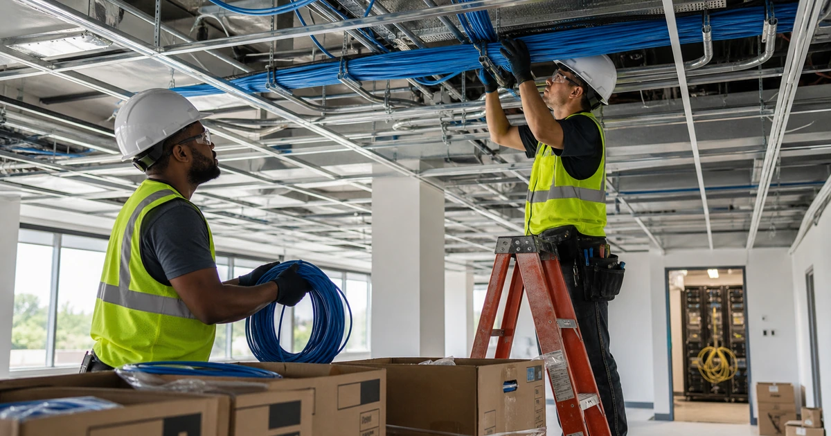
Protect cable during delivery and pulling, maintain the manufacturer’s bend radius and tension limits, keep twists and geometry intact, use approved supports, respect pathway fill, avoid crushing or tight staples, and maintain required separation from interference and power sources. Keep pathways neat and serviceable rather than dressing cables so tightly that maintenance damages them. Seal and firestop penetrations through rated assemblies using the approved system, and preserve records needed by the property owner.
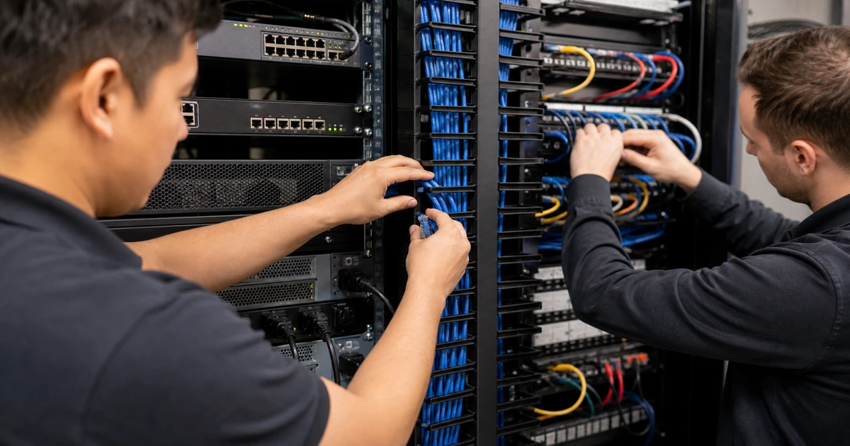
Terminate on compatible connecting hardware with consistent workmanship. Keep exposed conductor and untwist within the product instructions, secure strain relief, dress cables without blocking service access, and protect fiber cleanliness and bend control. Label both ends before bundles become difficult to trace. Use one identifier on the outlet, cable, patch-panel position, drawing, test record, switch map, and asset documentation. TIA’s administration work treats telecommunications identifiers and records as an infrastructure discipline, not a cosmetic step added after testing.
Certify the installed link using the correct adapters and project test limit. A permanent-link test covers the fixed infrastructure, while a channel result can include patch cords and has a different purpose. Fluke Networks describes certification as assurance that installed links meet defined industry requirements and can support the intended communications. Review individual results, marginal performance, wiremap, length, insertion loss, return loss, crosstalk, delay, and other required measurements. Correct failed links and retest them under the final identifier rather than delivering a folder that nobody reconciled with the installed plant.
- Cable handling: Control pulling force, bend radius, support, pathway fill, crushing, moisture, interference, and environmental exposure.
- Termination: Use matched components, manufacturer instructions, clean workmanship, strain relief, serviceable dressing, and fiber hygiene.
- Administration: Apply one durable identifier across the outlet, cable, panel, drawing, test record, port map, and service inventory.
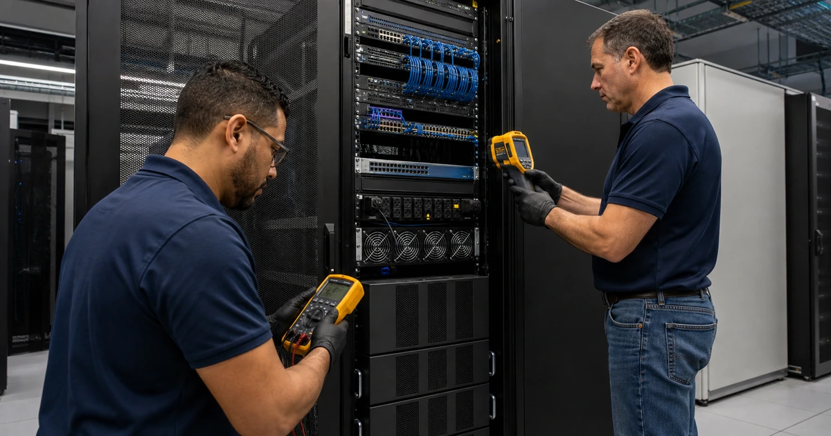
- Certification: Set the correct link model and limit, calibrate and inspect equipment, test every required link, and review actual results.
- Remediation: Diagnose failures, repair the cause, retest under final conditions, and replace superseded results in the handoff set.
Installation quality is proven by traceable passing results and clear administration, not by a link light or a successful speed test from one device.
Commission switching, PoE, voice, Wi-Fi, and the user cutover
Patch each link according to the approved port map and verify the switch configuration before users arrive. Confirm access and voice VLAN behavior, port security, authentication, discovery, speed, duplex, PoE capability, uplink capacity, monitoring, and device naming for the actual endpoint. Cisco’s current voice VLAN guidance describes how an access port can carry IP phone voice traffic and attached data traffic with defined tagging and quality settings. Apply the equivalent supported design for the selected phone and switch platform, then verify what the endpoint actually receives.
Power over Ethernet needs a documented port and system budget. Compare phone, wireless access point, camera, and other powered-device requirements with the port standard, switch capacity, power supply, redundancy, UPS, and growth reserve. Cisco notes that insufficient available or configured power can cause the switch to deny or remove power. For higher-power applications, also ensure the installed cabling and connections meet the project requirements for power delivery and heat conditions. Test representative peak functions, including phone startup, access-point radios, camera illumination, and accessory loads.
Complete a controlled cutover. Verify wired access, phone registration, inbound and outbound calling, emergency-address responsibility, voicemail, transfers, conference functions, quality during busy network conditions, Wi-Fi coverage, printing, cameras, and any specialized endpoint. Record switch ports, device identities, extension assignments, exceptions, and support contacts. Train the local coordinator on patching and escalation, then update drawings and records for every field change made during commissioning.
- Port configuration: Verify data and voice VLANs, authentication, security, discovery, speed, duplex, PoE, naming, and monitoring.
- Power validation: Compare per-device demand with port capability, total switch budget, power supplies, UPS, and reserve.
- Voice acceptance: Test registration, calls, transfers, voicemail, conferencing, addressing responsibility, failover, and quality under load.
- Data acceptance: Test wired service, internet, internal resources, Wi-Fi uplinks, printers, cameras, displays, and specialized systems.
- Final records: Reconcile as-builts, test results, patching, switch maps, inventories, extensions, exceptions, and support ownership.
The cutover is complete when every outlet is traceable, the intended endpoint receives the correct network and power service, and users can complete their real calls and work without hidden exceptions.
Data and voice cabling installation from one accountable team
ALLMSP can survey the property, design outlets and pathways, install copper and fiber, build racks and patch panels, label and certify links, configure switching and PoE, prepare VoIP and Wi-Fi, complete user cutover, and deliver as-built documentation with our in-house team.
Because we also support endpoints, networks, phones, cybersecurity, cameras, cloud systems, and internet connectivity, the installation is designed for the services that will use it. When a problem crosses cabling, a switch, a phone, an access point, or a provider, the investigation remains connected instead of being divided into unrelated tickets.
- Design: Plan work areas, rooms, pathways, media, racks, power, switches, PoE, testing, cutover, and future capacity.
- Build: Install, terminate, label, certify, patch, configure, commission, and document the complete system.
- Support: Troubleshoot links and services, manage changes, maintain records, plan growth, and coordinate providers.
Structured cabling installation references
Use the current project specification, applicable standards, manufacturer instructions, and local requirements, then retain test evidence that matches the final installed links.
- TIA TR-42 telecommunications cabling systems. Identifies standards work covering premises cabling, pathways, spaces, administration, copper, fiber, bonding, grounding, and data centers.
- TIA premises telecommunications infrastructure. Describes topology, architecture, design, installation, testing, performance, and support for voice, data, video, and low-voltage applications.
- Fluke Networks cabling certification overview. Explains permanent-link, channel, patch-cord, and modular-plug test models and why certification differs from basic verification.
- Cisco Power over Ethernet guidelines. Documents power allocation, device requests, available budget, faults, and port behavior.
- Cisco voice VLAN configuration guide. Shows current access-port voice and data handling, priority tagging, verification, and supported switch configuration concepts.
Data and voice cabling installation FAQs
What is structured cabling?
Structured cabling is a planned system of telecommunications rooms, backbone and horizontal pathways, copper or fiber links, outlets, panels, patching, administration, testing, and records that supports many networked services.
How many data outlets should an office install?
Count current workstations, phones, access points, cameras, printers, conference devices, displays, building systems, flexible spaces, and future growth. The right number follows the floor plan and operating model.
Can one cable support a computer connected through an IP phone?
Many supported phone and switch designs allow a computer to connect through the phone while voice and data use different logical policies. Confirm bandwidth, VLAN, QoS, security, PoE, and vendor compatibility before relying on it.
What is the difference between cable verification and certification?
Verification can find basic faults and length. Certification compares an installed link with a defined standards-based performance limit using appropriate test equipment and produces traceable results.
Why should every network cable be labeled at both ends?
Consistent identifiers connect outlets to panels, test records, switch ports, drawings, devices, and support history. This shortens moves and repairs and reduces accidental disconnections.
Does every new cable need to be tested?
The project should define required testing and acceptance. For a professional structured cabling installation, each delivered permanent link should have a traceable result appropriate to its specified media and performance.
What determines whether a device can receive Power over Ethernet?
The powered device, switch port, PoE standard, switch power supply, total budget, cable plant, connections, feature load, and upstream power all affect reliable delivery.
What documentation should come with a cabling project?
Expect final floor plans, pathway and room drawings, cable schedules, labels, panel and port maps, test results, rack elevations, fiber details, photos, warranties, exceptions, cutover records, and support contacts.
Can ALLMSP install cabling and configure the network in house?
Yes. ALLMSP can design and install cabling, racks, panels, fiber, switches, PoE, Wi-Fi, phones, security settings, testing, documentation, training, and ongoing support with its own team.
Where does ALLMSP provide structured cabling service?
ALLMSP serves Lawrenceville, Suwanee, Gwinnett County, Metro Atlanta, and other Georgia locations according to building access, project scope, and scheduling.