


























































































































































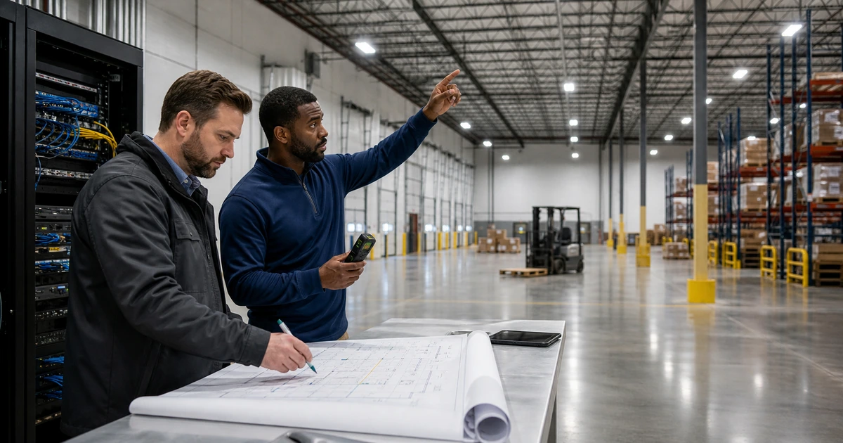
A commercial camera installation should begin with the event the business needs to understand, not with a camera count. Watching a loading area, recognizing a person at an entrance, reading a vehicle plate, confirming a point-of-sale transaction, and reviewing a safety incident require different fields of view, mounting positions, lighting, frame rates, retention periods, and privacy decisions. A wide image can show that something happened while still lacking the detail needed to determine who or what was involved.
The wiring plan connects those operational needs to cable routes, telecommunications spaces, switch ports, Power over Ethernet capacity, recorder and storage design, network security, backup power, and future service access. Decisions made before ceilings close are much less expensive than moving cameras, adding power, or tracing undocumented cable after the building is occupied.
ALLMSP plans and implements business security camera wiring in house for Lawrenceville, Suwanee, Gwinnett County, Metro Atlanta, and organizations throughout Georgia. We coordinate the physical pathway, network, camera, recording, cybersecurity, documentation, testing, and support requirements as one system so the finished installation can produce useful evidence when it matters.
Turn each security objective into a testable camera view
- Define the event: Identify the people, vehicles, transactions, doors, equipment, hazards, or property conditions the business needs to review.
- Set the viewing requirement: Decide whether a scene must provide awareness, observation, recognition, identification, plate detail, or transaction context.
- Survey the environment: Record mounting surfaces, lighting changes, glare, weather, obstructions, movement, privacy boundaries, cable routes, and service access.
- Engineer the pathway: Map approved cable types, lengths, penetrations, supports, pathways, labels, patching, grounding needs, and telecommunications-room termination.
- Budget the platform: Calculate switch ports, PoE demand, uplinks, bandwidth, recorder throughput, storage, retention, backup power, licensing, and growth capacity.
- Define acceptance: Specify day and night image tests, playback, search, export, alerts, failover, labeling, cable results, documentation, and owner signoff.
Survey scenes for usable evidence, not decorative coverage
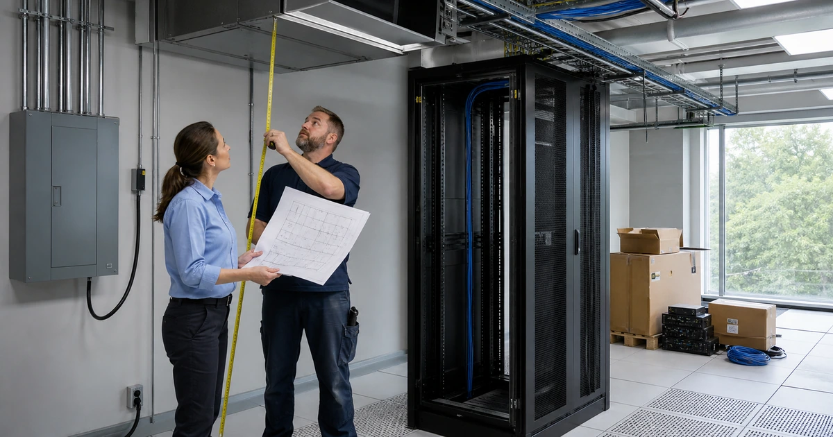
Walk the property with facilities, operations, security, IT, and the people who investigate incidents. For each location, write a plain-language objective such as identify a person entering after hours, confirm which vehicle reached a gate, review activity around a cash drawer, or verify whether a machine guard was in place. Mark the target area on a floor plan and note the distance, target height, mounting height, likely direction of travel, expected speed, and the smallest detail that must remain visible. This prevents a broad overview camera from being mistaken for an identification camera.
Evaluate the scene under the conditions that make it difficult. Entrances may have strong backlight during the day. Parking areas can become dark beyond the reach of built-in infrared illumination. Rain, headlights, foliage, seasonal sun, reflective clothing, dust, vibration, and moving equipment can change the usable image. Axis guidance connects image usability to pixel density, field of view, mounting location, motion, lighting, and environmental conditions. Use those variables to select and aim equipment, then test with representative people and vehicles instead of relying only on a planning drawing.
Discuss privacy before installation. Exclude private areas, avoid unnecessary views into neighboring property, decide whether audio is appropriate, define who can view live and recorded video, and document retention and disclosure rules with the business’s legal and compliance advisers. Cameras should support a stated safety, security, operational, or loss-prevention purpose. A camera placed simply because a cable path is convenient often creates weak evidence and avoidable privacy risk.
- Scene objective: Write what an authorized reviewer must be able to determine from the recording.
- Target detail: Define the needed level of visual detail at the actual subject distance and position.
- Light study: Check daytime, nighttime, backlight, reflections, infrared behavior, headlights, and changing weather.
- Obstruction review: Account for doors, signs, shelving, trees, vehicles, displays, equipment, and future construction.
- Privacy boundary: Document excluded spaces, masking needs, audio decisions, access limits, retention, and disclosure responsibility.
The survey is complete when every proposed view has a business owner, a defined purpose, an expected detail level, a privacy decision, and a repeatable acceptance test.
Design cabling, PoE, switching, bandwidth, storage, and resilience together
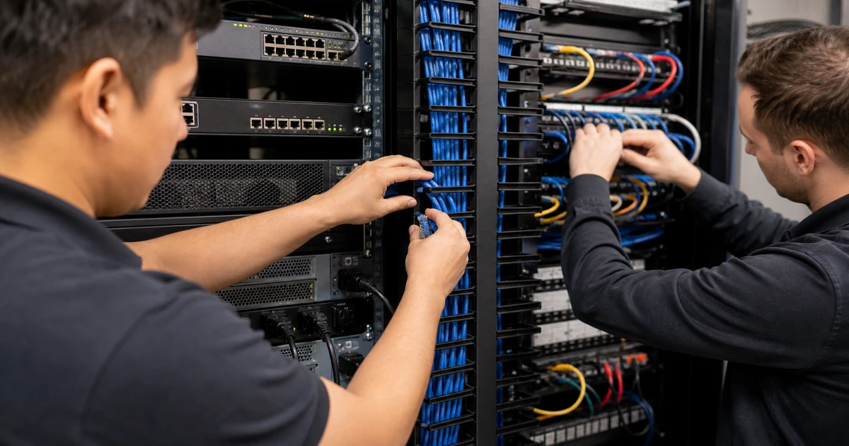
Create a cable schedule that maps each camera to a labeled outlet, horizontal cable, patch-panel position, switch port, network segment, recorder, and physical location. Select cable and pathway materials for the environment, including plenum, riser, outdoor, wet-location, ultraviolet, conduit, surge, separation, and firestopping requirements where applicable. Keep cable supported and serviceable, protect bend radius and terminations, and coordinate penetrations with the responsible building professionals. Local code, permit, licensing, and firestopping requirements should be confirmed for the specific property and scope before work begins.
Power over Ethernet must be planned at both the individual port and whole-switch level. Record the camera’s required PoE standard and maximum demand with accessories active, including heaters, infrared illuminators, microphones, speakers, or pan-tilt-zoom movement. Compare that demand with the switch model, power supply, port capabilities, total PoE budget, redundancy, and planned growth. Cisco documents that a switch can deny or remove power when the request exceeds configured or available capacity. Fluke Networks also emphasizes cable resistance and resistance unbalance because a link can pass ordinary data while still delivering unreliable power under load.
Estimate bandwidth and storage from the actual cameras, resolutions, codecs, frame rates, scene activity, recording modes, analytics, and retention targets. Do not multiply a marketing maximum by the camera count and assume the result describes real operation. Validate recorder ingest and playback limits, storage protection, export capacity, remote-viewing traffic, uplink utilization, time synchronization, and backup power. Retain headroom for firmware changes, busier scenes, additional cameras, and incident exports without starving ordinary business traffic.
- Cable schedule: Map camera, outlet, cable ID, patch panel, switch, port, VLAN, recorder, and physical route.
- PoE worksheet: Record device class, maximum watts, accessory load, switch allocation, power-supply capacity, and reserve.
- Network design: Define segmentation, addressing, time, name resolution, management access, uplinks, monitoring, and remote access.
- Storage model: Calculate normal and peak bitrate, recording schedule, retention, protected capacity, playback, export, and recovery needs.
- Power continuity: Size UPS coverage for switches, recorders, storage, management equipment, cooling, and controlled shutdown.
The infrastructure plan is ready when every camera has a supported path for data and power and the complete system can meet recording and retention goals during realistic load.
Commission every link, view, recording path, alert, and handoff document
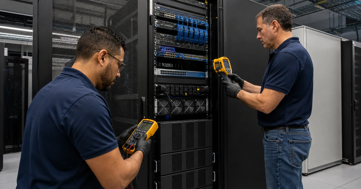
Test and document the permanent cable links before relying on cameras as the test instrument. Match the test method and limit to the installed cabling and project requirement. Review wiremap, length, performance, and PoE-related results where specified, then correct failures rather than hiding them behind a device that happens to connect. Label both ends of each link, patch panels, switch ports, outlets, camera locations, recorder connections, and power dependencies using one consistent scheme that matches the drawings and asset record.
Commission each camera at the intended mounting position. Focus and aim it against the written scene objective, then test live view, recording, playback, search, export, timestamp, motion, analytics, privacy masks, audio decisions, and alerts. Repeat critical image checks after dark and during challenging lighting. Confirm that the recorder continues after a brief utility interruption, that an authorized person can retrieve evidence, and that a failed camera, full volume, lost uplink, or interrupted recording creates an actionable notification.
Deliver as-built drawings, cable results, camera and network inventory, port map, addressing plan, configuration backup, firmware baseline, warranty information, storage and retention settings, user roles, escalation contacts, maintenance schedule, and evidence-export procedure. Train operations and authorized reviewers with a real scenario. The final acceptance record should show that the system met each stated objective, not merely that every camera displayed a picture on installation day.
- Cable evidence: Retain project-specific test results tied to the permanent link and its final label.
- View validation: Capture approved day and night reference images for each camera’s required scene and detail.
- Recording proof: Test search, playback, synchronized time, export, retention, storage alerts, and access by authorized roles.
- Failure testing: Simulate an unplugged camera, lost uplink, PoE interruption, storage warning, and short power event where safe.
- Operational handoff: Provide drawings, inventories, credentials custody, backups, procedures, training, and support ownership.
A camera project is finished only when the cabling is documented, the views satisfy their purposes, recordings can be retrieved, failures are visible, and the business can operate the system responsibly.
Security camera wiring design and installation from ALLMSP
ALLMSP can complete the site survey, coverage plan, camera and recorder selection, cable-path coordination, structured wiring, rack and switch work, PoE planning, network segmentation, storage sizing, installation, configuration, testing, labeling, documentation, training, and continuing support in house.
Because our team also supports networks, cybersecurity, backup power, cloud services, and business systems, we can trace a camera problem across the complete path. That includes the endpoint, cable, patching, switch port, PoE supply, VLAN, uplink, recorder, storage, identity, remote access, and user workflow rather than stopping at the first device that responds.
- Plan: Translate business risks and operational questions into views, pathways, power, bandwidth, storage, privacy, and acceptance criteria.
- Install: Build and label the cable plant, mount and aim cameras, configure the network and recorder, and commission the system.
- Support: Monitor health, maintain firmware and access, troubleshoot failures, test evidence retrieval, and update documentation.
Technical references for camera-system planning
Use current manufacturer and standards-organization guidance to validate design assumptions, then prove the result in the property’s real lighting, traffic, network, and operating conditions.
- Axis pixel density guidance. Explains how field of view, mounting location, target distance, and pixel density relate to operational requirements.
- Axis image usability guidance. Covers lighting, motion, environmental conditions, camera selection, and testing for useful forensic detail.
- Cisco PoE guidelines. Documents device power requests, port behavior, available budget, power faults, and switch allocation.
- Fluke Networks PoE installation guide. Describes powered-device compatibility, cable certification, resistance unbalance, and field troubleshooting.
- ONVIF Profile T. Summarizes interoperable advanced video features such as streaming, imaging, metadata, events, HTTPS, and PTZ support.
Security camera wiring planning FAQs
How many security cameras does a business need?
The count follows the required views. Define the doors, lanes, transactions, assets, hazards, and incident questions first, then choose positions and camera types that deliver the required detail without unnecessary overlap.
Why is a wide camera view not always useful evidence?
A wide scene spreads available pixels across more space. It may show activity while failing to preserve facial, vehicle, plate, transaction, or object detail at the target distance.
Should camera locations be tested at night?
Yes. Infrared reflection, darkness, headlights, motion blur, noise, glare, and changing exposure can produce a very different result after dark. Critical views should be accepted in their hardest realistic conditions.
What belongs in a camera wiring plan?
Include scene objectives, floor plans, device locations, cable routes, labels, pathways, patch panels, switch ports, PoE loads, VLANs, addressing, bandwidth, storage, retention, backup power, access, alerts, tests, and owner signoff.
How should PoE capacity be calculated for cameras?
Compare each device’s maximum requirement, including active accessories, with its port capability and the switch’s total available budget. Add reasonable reserve and test behavior under representative load.
Does a working camera prove the cable is good?
No. A device may connect despite marginal workmanship, damaged pairs, excess resistance, or insufficient performance. Test the installed link to the project requirement and retain results tied to the final label.
How is camera video retention sized?
Use camera count, resolution, codec, frame rate, scene activity, recording mode, target bitrate, retention days, storage protection, overhead, and growth. Validate the recorder’s ingest, playback, and export limits too.
What documentation should be delivered after installation?
Expect as-built drawings, cable and port maps, test results, device inventory, addressing, network design, configuration backup, reference views, roles, retention settings, alert paths, warranties, maintenance, and evidence-export procedures.
Can ALLMSP install and support the complete camera system in house?
Yes. ALLMSP can handle planning, wiring, racks, switching, PoE, cameras, recording, storage, network security, testing, documentation, training, and ongoing support with its in-house team.
Where does ALLMSP provide security camera wiring services?
ALLMSP serves businesses in Lawrenceville, Suwanee, Gwinnett County, Metro Atlanta, and other Georgia locations based on project scope and scheduling.