



























































































































































A commercial cabling project succeeds when every installed link supports the intended application, can be identified at both ends, follows an approved pathway, passes the required test, and has a record that facilities and IT can use. Counting drops or seeing a link light does not establish that outcome. The pathway, cable, connector, termination, administration, test method, and active equipment all contribute to performance.
Planning and acceptance must begin before walls close or furniture arrives. Technology, construction, electrical, fire protection, security, audiovisual, furniture, and business teams need a shared outlet and pathway plan. Changes should be documented while they are still inexpensive. At turnover, the customer should receive more than a bundle of test files with identifiers that do not match the labels in the room.
ALLMSP plans, installs, tests, and documents commercial network cabling through its in-house team for Lawrenceville, Suwanee, Gwinnett County, Metro Atlanta, and Georgia organizations. We can coordinate copper, fiber, racks, wireless access points, phones, cameras, workstations, printers, point of sale, carrier services, and network equipment as one functioning project.
Build every cable path for installation quality and verifiable acceptance
- Define requirements: List devices, applications, bandwidth, PoE, location, mounting, environment, redundancy, growth, standards, and acceptance.
- Coordinate pathways: Review plans, ceilings, walls, furniture, access, supports, fill, separation, penetrations, grounding, and future service.
- Control materials: Specify cable, connectors, patch panels, fiber, ratings, color, supports, labels, racks, and approved substitutions.
- Inspect installation: Check pulls, bend radius, tension, damage, support, bundling, slack, termination, separation, and firestopping.
- Test correctly: Use the required permanent-link or channel method, limits, adapters, calibration, identifiers, and retest procedure.
- Accept records: Reconcile labels, drawings, test results, photographs, rack elevations, exceptions, punch items, and business-service validation.
Translate device and application needs into an installable pathway plan
Inventory every intended endpoint and likely growth. Include work areas, phones, wireless access points, cameras, door systems, printers, point-of-sale equipment, displays, conference rooms, building systems, servers, uplinks, carrier demarcations, and spare capacity. Record location, height, mounting, cable type, port count, data rate, PoE need, environmental condition, criticality, redundancy, and active-equipment dependency. Confirm whether furniture, floor boxes, outdoor spaces, warehouses, ceilings, elevators, or secure areas change the installation method.
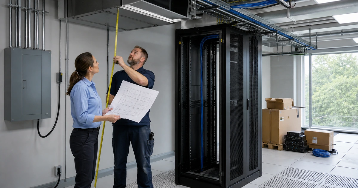
Mark pathways and telecommunications spaces on coordinated drawings. Review route length, access, support, bend control, fill, transitions, sleeves, conduits, trays, penetrations, separation from power and interference sources, grounding and bonding needs, fire-rated assemblies, and future maintenance. Resolve conflicts with lighting, ductwork, sprinklers, electrical, plumbing, structure, and architectural finishes before installation. Preserve access to junctions, pathways, panels, and service loops after ceilings and millwork are complete.
Write acceptance requirements before procurement. Specify the applicable standards and editions, cable category or fiber type, component compatibility, performance class, jacket or environmental rating, termination configuration, labels, color use, patching, test method, limits, instrument requirements, calibration, deliverable format, warranty needs, approved substitutions, and correction process. Avoid choosing a category number without confirming the application, length, environment, power delivery, pathway, active equipment, and lifecycle plan.
- Endpoint schedule: Record device, room, position, mounting, ports, speed, PoE, environment, criticality, owner, and future quantity.
- Pathway review: Coordinate route, access, length, support, fill, bends, separation, penetrations, fire rating, and maintenance.
- Space design: Plan racks, panels, fiber protection, cable managers, equipment depth, power, grounding, cooling, lighting, and growth.
- Material schedule: Define cable, connectors, panels, enclosures, supports, ratings, colors, labels, patch cords, and substitution control.
- Acceptance plan: State test configuration, standard, limit, instrument, calibration, result format, identifiers, retest, and punch process.
The pathway plan is complete when installers can build it, other trades can coordinate around it, and the customer can verify the intended result.
Inspect pulling, support, termination, labels, and physical workmanship
Inspect materials at delivery and protect them through installation. Verify manufacturer, type, rating, quantity, lot information where required, and compatibility with the specification. Store cable within environmental limits and protect reels or boxes from damage. During pulls, manage tension, bend radius, kinks, twists, abrasion, sharp edges, crushing, and pathway capacity. Use approved supports at appropriate spacing and do not rest telecommunications cabling on ceilings, sprinkler pipe, electrical conduit, or unrelated building systems.
Review terminations before they disappear into plates or panels. Maintain pair geometry and jacket position according to component instructions, use the specified pinout consistently, protect fiber end faces, inspect and clean connectors with appropriate procedures, manage slack, and provide strain relief. Avoid reusing damaged connectors or forcing unsuitable field repairs. Confirm outlet orientation and mounting so furniture, equipment, or user movement will not crush plugs and cords.
Apply durable labels at both ends using the project’s identifier scheme. The identifier should connect the outlet, room or area, pathway where needed, telecommunications room, rack, patch panel, and port. Labels must remain readable after installation and match drawings and test records exactly. Photograph concealed pathways and firestopping before closure when required. Record changes immediately so field conditions do not diverge from design and produce a costly tracing project at turnover.
- Material check: Verify manufacturer, part, performance, environmental rating, compatibility, quantity, condition, and approved substitution.
- Pull quality: Control tension, bends, kinks, twists, abrasion, sharp edges, crushing, pathway fill, and environmental exposure.
- Cable support: Use suitable independent supports, protect transitions, maintain access, and avoid unrelated building systems.
- Termination check: Inspect pinout, pair geometry, jacket, strain relief, connector seating, fiber cleanliness, slack, and physical protection.
- Label match: Reconcile both ends, panel, room, rack, drawings, test record, outlet schedule, and active-equipment plan.
Good workmanship protects performance and makes the later test result explainable, repeatable, and connected to a physical link the customer can find.
Certify installed links and verify the network service before acceptance
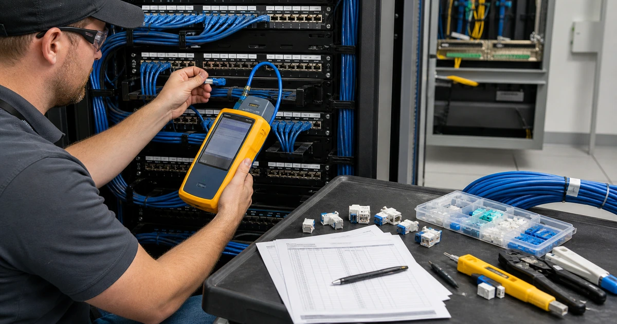
Select the test configuration required by the project. A permanent-link test evaluates installed horizontal cabling without the equipment patch cords, while a channel test includes defined connecting cords and components. Confirm the exact standard, edition, category or class, fiber parameters, limit, adapter type, reference procedure, instrument software, and calibration. Test every required link under its unique identifier. A wiremap tester can find some faults, but it does not replace performance certification when certification is required.
Review the result set rather than accepting a pass summary. Check identifier completeness, test limit, measured length, propagation and delay behavior, insertion loss, return loss, crosstalk measures, shield continuity where applicable, fiber loss and polarity, marginal results, unexpected adapters, and missing links according to the specified test. Diagnose and repair failures, then preserve original and passing retest results with the corrective note. BICSI guidance states that installed cabling should be measured with an appropriate field-test instrument according to applicable standards.
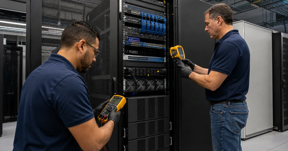
Finish with business-service validation and reconciled turnover. Patch approved links to configured switch ports, then verify speed, errors, VLAN, PoE, wireless, phones, cameras, printers, workstations, point-of-sale devices, and other intended applications. Complete the punch list, inspect rooms and pathways, remove debris, close penetrations correctly, and confirm labels. Deliver editable schedules where practical, drawings, rack elevations, photographs, test exports, equipment records, exceptions, warranty information, and owner training.
- Test definition: Confirm permanent link or channel, medium, performance class, edition, limit, adapters, reference, and calibration.
- Result review: Check every ID, pass status, length, required electrical or optical measures, marginal results, and missing tests.
- Failure correction: Identify cause, inspect path and termination, repair appropriately, retest, and retain before and after evidence.
- Active validation: Confirm switch port, speed, errors, VLAN, PoE, addressing, and the intended endpoint or application.
- Turnover package: Provide labels, schedules, drawings, rack views, photographs, test exports, exceptions, warranty, spares, and training.
Acceptance should prove that each labeled physical link passed the specified test and supports the business device and service it was built to carry.
Commercial network cabling installation and testing from ALLMSP
ALLMSP can survey sites, develop outlet schedules, coordinate pathways, specify copper and fiber, install and terminate cabling, label infrastructure, perform required testing, correct failures, configure active equipment, validate endpoints, and deliver useful turnover records with our own team.
We support new construction, renovations, relocations, expansions, network upgrades, wireless deployments, phones, cameras, access systems, point of sale, and production environments in Lawrenceville, Suwanee, Gwinnett County, Metro Atlanta, and across Georgia.
- Design: Translate endpoints, applications, bandwidth, power, environment, redundancy, growth, and acceptance into plans.
- Install: Coordinate pathways, materials, pulls, supports, terminations, labels, protection, inspections, and changes.
- Certify: Run specified tests, correct failures, reconcile records, configure network ports, and validate business services.
Official network cabling design and test references
Project specifications should cite the standards, editions, codes, manufacturer instructions, field-test limits, and qualifications that apply to the facility. Verify current requirements before design and acceptance.
- TIA-568 cabling standards family. Covers commercial building telecommunications cabling standards developed through TIA.
- ANSI/TIA-568.2-E publication announcement. Confirms the updated balanced twisted-pair cabling and components standard released in 2024.
- TIA standards announcements. Provides current notices for published standards, ballots, reaffirmations, and revisions.
- IEEE 802.3 Ethernet Working Group. Provides the official working-group home for Ethernet standards and active projects.
- BICSI field-testing reference. Addresses appropriate field testing for installed balanced copper, optical fiber, and other media.
Commercial network cabling installation FAQs
When should network cabling planning begin in a construction project?
Begin during early design so pathways, rooms, power, ceilings, furniture, walls, fire-rated assemblies, equipment, outlet locations, and other trades can be coordinated before closure.
How many cable drops should an office install?
Base quantity on current endpoints, workstation and room layouts, wireless, phones, cameras, building systems, redundancy, spare capacity, and realistic growth rather than one fixed ratio.
When should fiber be used instead of copper?
Consider distance, bandwidth, electrical environment, building-to-building links, backbone design, redundancy, future capacity, equipment compatibility, installation, testing, and lifecycle cost.
Why does Power over Ethernet affect cabling design?
PoE adds power delivery, heat, bundling, switch budget, connector, cable, pathway, and device requirements that should be evaluated with current standards and manufacturer guidance.
What is the difference between wiremap and cable certification?
Wiremap checks conductor arrangement and basic faults. Certification measures the performance required by a specified cabling standard and link configuration using suitable field-test equipment.
What is a permanent-link test?
It tests the installed cabling between defined endpoints without the equipment patch cords, using adapters and limits specified for that test configuration.
Should every installed cable have a unique label?
Yes. The identifier should appear at both ends and match the outlet schedule, panel record, drawings, test result, and active network documentation.
What happens when a cable fails certification?
Inspect the route, length, damage, components, termination, test setup, adapters, instrument, and limit. Repair the cause appropriately, retest, and retain corrective evidence.
Can ALLMSP install cabling and configure the network equipment?
Yes. ALLMSP can coordinate pathways, install and test cabling, configure switching, VLANs and PoE, connect devices, validate applications, and document the final system.
Where does ALLMSP install commercial network cabling?
ALLMSP serves businesses in Lawrenceville, Suwanee, Gwinnett County, Metro Atlanta, and locations across Georgia with planned onsite installation.